background image

9

ECOWATER

S Y S T E M S

Installation & Sanitizing

9. PRESSURE TESTING FOR LEAKS,

PROGRAMMING THE CONTROLLER &

RINSING THE MEDIA

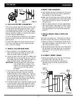
To prevent excessive air pressure in the water

softener and plumbing system, do the following

steps EXACTLY in order:
a

. Fully open two or more 

softened

cold water

faucets nearby the water softener.

b

. Place the bypass valve(s) in 

bypass

position (See

Figures 2 & 4).

c

. Fully open the main water supply valve.  Watch

until the flow from the opened faucets becomes

steady, with no spurting or air bubbles.

d

. After about three minutes, open a hot water faucet

for one minute, or until all air is expelled.

e

. Close all faucets and check your plumbing work for

leaks.

f

. Make sure the softener’s valve drain hose is

hooked up and the open end directed to a floor

drain, laundry tub or other suitable type of drain.

g

. Make sure the softener’s bypass valve is in the

bypass

position.

h

. Plug in the power supply.

i

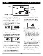
Program the electronic controller:

Follow the

steps on Pages 10 and 11 to program the electronic

controller with basic operating information, such as

time and water hardness.  After completing these

steps, continue with “j. Start a recharge”, below.

j

Start a recharge:

Press the RECHARGE button

and hold for 3 seconds, until “Recharge Now” flash-

es in the display and you hear the valve motor run

as the softener begins recharging.

k

. Once the unit is in backwash, place bypass

valve(s) into the 

service

position, as follows:

(1) SINGLE BYPASS VALVE: 

Slowly 

move the

valve stem toward 

service

position, pausing sev-

eral times to allow the unit to pressurize slowly.
(2) 3-VALVE BYPASS: Fully close the 

bypass

valve and open the 

outlet

valve.  

Slowly 

open

the 

inlet

valve, pausing several times to allow the

unit to pressurize slowly.

l

. Let the softener complete the backwash and fast

rinse cycles (takes 10-12 minutes).  When the

recharge cycle ends, the softener valve returns to

the service position.

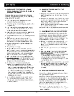
10. ADD WATER AND SALT TO THE

BRINE TANK

a

. Using a pail or garden hose, add about 3 gallons of

water into the brine tank.  DO NOT pour into the

brinewell.

b

. Add salt to the brine tank.  It is recommended to fill

the brine tank no more than 1/2 full.  Level the salt

when finished adding.  You can use most water

softener salts, but it must be clean.

Recommended nugget, pellet or coarse solar salts

have less than 1% impurities.

NOTE:

See page 14 for additional information on salt.

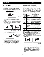
11. SANITIZING THE WATER SOFTENER

Care is taken at the factory to keep your EcoWater

Systems water softener clean and sanitary.  However,

during shipping, storage, installing and operating,

bacteria could get into the unit.  For this reason, sani-

tizing as follows is suggested* when installing.

a

. Remove the brinewell cover and pour about 1-1/2

oz. (2 to 3 tablespoons) of common household

bleach into the softener’s brinewell.  Replace the

brinewell cover.

b

. Make sure the bypass valve is in the 

service

posi-

tion.

c

Start a recharge:

Press the RECHARGE button

and hold for 3 seconds, until “Recharge Now”

flashes in the display and you hear the valve motor

run as the softener begins recharging.  This

recharge draws the sanitizing bleach into and

through the softener.  Any air remaining in the unit

is purged to the drain.

d

. After the recharge has completed, fully open a cold

water faucet, downstream from the softener, and

allow 50 gallons of water to pass through the sys-

tem.  This should take at least 20 minutes.  Close

the faucet.

12. RESTART THE WATER HEATER

Turn on the electric or fuel supply to the water heater,

and light the pilot, if applies.

NOTE:

The water heater is filled with hard water and,

as hot water is used, it refills with softened water.  In

a few days, the hot water will be fully conditioned.  To

have fully conditioned hot water immediately, wait

until the recharge (Step 11) is complete, then drain

the water heater until water runs cold.

*

Recommended by the Water Quality Association.  On

some water supplies, the EcoWater Systems unit may need

periodic disinfecting.

Содержание EEC 1502R25

Страница 1: ... 7349023 Rev C 3 11 15 EcoWater Systems LLC P O Box 64420 St Paul MN 55164 0420 www ecowater com Designed Engineered Assembled in the U S A Systems tested and certified by the Water Quality Association against CSA B483 1 Systems tested and certified by NSF International against NSF ANSI Standard 44 for hardness reduction and efficiency ...

Страница 2: ...ste Electrical and Electronic Equipment WEEE require ments This directive or similar laws are in place nationally and can vary from region to region Please refer to your state and local laws for proper disposal of this equipment Follow the installation instructions carefully Failure to install the water softener properly voids the warranty Before you begin installation read this entire manual Then...

Страница 3: ... flow rate may affect capacity and efficiency performance Capacity to remove clear water iron is substantiated by WQA test data State of Wisconsin requires additional treatment if water supply contains greater than 5 ppm clear water iron u Canada working pressure limits 1 4 7 0 kg cm These units conform to NSF ANSI 44 for the specific performance claims as verified and substantiated by test data T...

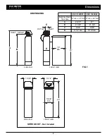
Страница 4: ...0 Nominal Resin Tank Size 8 dia x 40 tall 9 dia x 40 tall A 45 1 2 47 B 41 3 8 41 3 4 C 3 3 8 3 3 4 D 8 1 4 dia 9 1 4 dia FIG 1 39 FRONT VIEW SIDE VIEW C D DIMENSIONS 18 DIA INLET OUTLET INLET OUTLET A B 10 5 8 DIA 48 13 1 4 12 3 8 FRONT VIEW SIDE VIEW SHROUD KIT Not Included 48 FRONT VIEW SIDE VIEW 10 5 8 DIA 12 3 8 13 1 4 ...

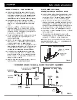
Страница 5: ...ation plumbing wiring etc are as well protected from the elements contamination vandalism etc as when installed indoors Keep the softener out of direct sunlight The sun s heat may soften and distort plastic parts TOOLS PIPE FITTINGS OTHER MATERIALS YOU WILL NEED ALWAYS install an EcoWater Systems bypass valve or a 3 valve bypass system Bypass valves let you turn off water to the softener for repai...

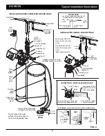
Страница 6: ...s supplied by installer 1 NPT Adaptor 2 not included 1 NPT Installation Adaptor 2 EcoWater Bypass Valve Clip 4 O Ring Seal 2 1 NPT Adaptor 2 not included Clip 2 O Ring Seal 2 1 NPT Installation Adaptor 2 Valve INLET 1 1 2 Air Gap 1 1 2 Air Gap 1 1 2 Air Gap LAUNDRY TUB SUMP STAND PIPE To standpipe sump laundry tub or other suitable drain CONNECTING A RIGID VALVE DRAIN TUBE Compression Fitting 1 4 ...

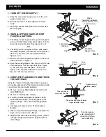
Страница 7: ... THE SOFTENER Using the Typical Installation Illustration on page 6 as a guide observe all of the following cautions while you connect inlet and outlet plumbing Be sure incoming hard water is directed to the valve INLET port Be sure to install bypass valve s If making a soldered copper installation do all sweat soldering before connecting pipes to the softener fittings Torch heat will damage plast...

Страница 8: ... 4 will maintain ground continuity If you use the plastic bypass continuity is broken To restore the ground do either step 4a or 4b following a Use the EcoWater ground clamp kit not included to make a jumper across the inlet and outlet pipes See Figure 9 b Install a 4 copper wire across the removed sec tion of main water pipe securely clamping at both ends parts not included 5 INSTALL VALVE DRAIN ...

Страница 9: ...returns to the service position 10 ADD WATER AND SALT TO THE BRINE TANK a Using a pail or garden hose add about 3 gallons of water into the brine tank DO NOT pour into the brinewell b Add salt to the brine tank It is recommended to fill the brine tank no more than 1 2 full Level the salt when finished adding You can use most water softener salts but it must be clean Recommended nugget pellet or co...

Страница 10: ...ead down sets the time back Be sure AM or PM is correct NOTE Press buttons and quickly release to slowly advance the display Hold the buttons down for fast advance 2 When the correct time is displayed press the SELECT button and the display will change to show the Hardness screen 2 Press the á UP or â DOWN buttons to set the value of your water s hardness in grains per gallon gpg NOTE If your wate...

Страница 11: ...set regenera tion start time 2 00 AM or as set If you decide to cancel this regeneration before it starts touch the same button once more VACATION NOTE EcoWater demand controlled water softeners regen erate only while water is being used and softening capacity must be restored For this reason the unit will not regenerate when you are away from home for extended periods FIG 18 NORMAL OPERATION Duri...

Страница 12: ...or or chemical feeder It provides a 28V DC up to 300 mA current from termi nal J4 on the electronic control board see Schematic on Page 17 The table below explains the choices available for when the auxiliary output will be on dur ing various portions of the recharge cycle SELEC TION NAME AUXILIARY OUTPUT FUNCTION OFF Off Remains off indefinitely BP Bypass On during the entire recharge CL Chlorine...

Страница 13: ...evel in the tank This will also assure that the softener is com pletely recharged and ready to provide softened water again Check the water level in the tank by looking down the brinewell If the water level does not drop after a recharge the problem has not been resolved RESIN BED CLEANING If the water supply contains clear water iron regular resin bed cleaning is needed to keep the bed from coati...

Страница 14: ...alts have an additive to help a water softener handle iron in the water supply Although this may help keep the resin bed clean it may also release corrosive fumes that will weaken and shorten the life of some EcoWater Systems softener electronic parts Iron Out salt is safe to use on two tank models BREAKING A SALT BRIDGE Sometimes a hard crust or salt bridge forms in the brine tank This is usually...

Страница 15: ...ATER S Y S T E M S Troubleshooting FIG 27 AUTOMATIC ELECTRONIC DIAGNOSTICS This softener has a self diagnostic function for the electrical system The computer monitors electronic components and circuits for correct operation If a malfunction occurs an error code appears in the dis play The chart below shows the error codes that could appear and the possible malfunctions for each code Code Possible...

Страница 16: ...echarges initiated by this electronic control since the model code number was entered 5 Press the SELECT button and hold in for 3 sec onds until the model code shows in the display The model code should be EC25 for Model EEC 1502R25 or EC40 for Model EEC 1502R40 If the wrong number shows the softener will operate on incorrect configuration data 6 To change the code number Press the á UP or â DOWN ...

Страница 17: ... S Y S T E M S Wiring Schematic FIG 36 NO Valve Motor Position Switch NC OUT 5 GND Power Supply Back of Electronic Controller PWA Power In Pos Turbine Motor Turbine Sensor 28V DC Auxiliary Output J4 28V DC 120V AC 60 Hz C org grn ...

Страница 18: ...18 SOFTENER EXPLODED VIEW EEC 1502R25 EEC 1502R40 ECOWATER S Y S T E M S Repair Parts 1 Valve Assembly See Pages 20 23 for parts 3 10 11 12 14 13 5 27 4 28 18 22 19 21 20 2 23 24 25 26 17 16 15 6 7 8 9 ...

Страница 19: ...R25 14 0502272 Resin 1 cu ft standard mesh Key No Part No Description 15 1183000 Tank Foot 8 Model EEC 1502R25 7226039 Tank Foot 9 Model EEC 1502R40 16 7310210 Brine Valve Assembly 17 7327568 Float Stem Guide Assembly 18 7345663 Cover Brine Tank 19 7155115 Cover Brinewell 20 7109871 Brinewell 7331698 Brinewell Mounting Hardware Kit includes Key Nos 21 22 21 á Washer 22 á Screw 23 7345590 Brine Tan...

Страница 20: ...S T E M S Repair Parts VALVE EXPLODED VIEW EEC 1502R25 70 91 51 50 52 53 55 56 59 58 57 60 61 66 67 62 63 64 68 69 70 71 72 73 74 75 65 76 77 79 78 80 81 82 Wear Strip Seal Cross section View 83 84 85 86 87 88 89 90 54 ...

Страница 21: ...ck of 20 71 7278442 Installation Adaptor 3 4 single 2 req 7336606 Installation Adaptor 3 4 pack of 10 includes 10 ea of Key No 72 Key No Part No Description 72 7170288 O Ring 15 16 x 1 3 16 single 2 req 7336402 O Ring 15 16 x 1 3 16 pack of 20 7113040 Turbine Support Assembly includes 1 ea of Key Nos 73 74 2 ea of Key No 72 73 á Turbine Support Shaft 74 á Turbine 75 7082053 Valve Body 76 7081201 R...

Страница 22: ...03 104 105 106 107 108 109 110 111 112 117 118 140 113 114 115 119 120 116 127 121 145 123 121 122 123 124 125 126 128 129 131 130 132 133 134 135 136 137 138 139 141 142 143 144 22 ECOWATER S Y S T E M S Repair Parts VALVE EXPLODED VIEW EEC 1502R40 ...

Страница 23: ...336614 Installation Adaptor 1 pack of 10 includes 10 ea of Key No 123 123 7311127 O Ring 1 1 16 x 1 5 16 single 2 req 7336410 O Ring 1 1 16 x 1 5 16 pack of 20 Key No Part No Description 7290931 Turbine Support Assembly includes 1 ea of Key Nos 124 125 2 ea of Key No 123 124 á Turbine Support Shaft 125 á Turbine 126 7309811 Wire Harness Sensor 127 7081201 Retainer Nozzle Venturi 128 7171145 Valve ...

Страница 24: ...f your product This warranty is called the Perfect Ten and extends the three year warranty on the electronic FACEPLATE WIRING HARNESS DRIVE MOTOR POWER SUPPLY POWER CORD SENSOR HOUSING and MICRO SWITCHES to a total of TEN YEARS from the date of original installation Your local dealer will provide details regarding this warranty or will refer you to the factory for additional information Should you...

Отзывы: