


15
MANUALLY INITIATED ELECTRONIC
DIAGNOSTICS
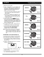
Use the following procedures to advance the softener
through the recharge cycles to check operation.
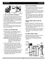
Remove the 2 screws holding the faceplate assembly
on top of the valve and lift the faceplate away from
the valve, to observe cam and switch operation dur-
ing valve rotation (See Figure 29).
1
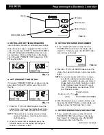
. Press and hold for 3 seconds the SELECT button,
until one of the screens shown in Figure 28 is dis-
played. If the valve is in service, fill, brining, back-
wash or fast rinse position (observe markings on
the valve cam), the display should show “000 - -”,
meaning the position switch is open. When the
valve is moving, the display should show “000 - P”,
meaning that the position switch is closed.
FIG. 28
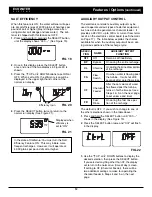
2
. The first 3 digits of the display in Figure 28 should
count upward whenever water is flowing through
the system.
3
. Use the RECHARGE button to manually advance
the valve into each position and check correct switch
operation (See Figures 31-35).
continued on the next page
ECOWATER
S Y S T E M S
Troubleshooting
FIG. 27
AUTOMATIC ELECTRONIC DIAGNOSTICS
This softener has a self-diagnostic function for the
electrical system. The computer monitors electronic
components and circuits for correct operation. If a
malfunction occurs, an error code appears in the dis-
play.
The chart below shows the error codes that could
appear, and the possible malfunctions for each code.
Code
Possible Problems
Err01 Motor, Valve Position Switch
Err03 Motor, Valve Position Switch, Wire Harness
Err04 Valve Position Switch
Err05 Electronic Control Board (PWA)
While an error code appears in the display, all buttons
are inoperable except the SELECT button. SELECT
remains operational so the service person can per-
form the Manually Initiated Electronic Diagnostics to
further isolate the problem.
TO REMOVE AN ERROR CODE:
1
. Unplug the power supply.
2
. Correct the problem.
3
. Plug the power supply back in.
4
. Wait for at least 8 minutes while the timer operates
the valve through an entire cycle. The error code
will return if the problem was not corrected.
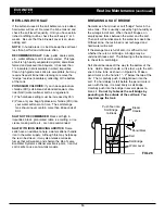
Switch
Water
Meter
FIG. 29
Position markers
(valve in service)
CAM
MOTOR
Position markers
(valve in service)
CAM
MOTOR
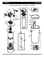
Model
EEC 1502R40
Model
EEC 1502R25