background image

Chapter IV Page 1 

IV.1. Changing the filters.


When  changing  the  filter  cartridge  make  sure  you  have  closed  the  seawater  inlet  sea  cock 
valve  before  unscrewing  the  bowl  filter  that  enables  you  to  remove  the  old  cartridge  and 
replace it with a new one which has the same specifications: 9 ¾ long, 5 micron calibrated 
filter.  We  do  not  recommend  another  type  of  cartridge,  it  could  allow  unwanted  particles 
enter the system. 
 
Once changed, screw the bowl filter back on and re-open the seawater inlet sea cock valve. 
Warning: use the filter wrench to close it. 
 
To replace the active carbon cartridge, disconnect the boat pressurized fresh water system,  
open  a  tab  to  not  leave  any  residual  pressure  in  the  circuit,  and    replace  the  active  carbon 
cartridge. Connect the boat pressurized fresh water system again. 


IV.2.  Membrane Replacement.


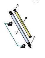
Follow these instructions to change the membrane, see diagram (Chapter IV Page 3) 


Before handling the unit, make sure there is no pressure in the circuit. If the pressure 
gauge indicates there is some, wait until it disappears.  


Dismantle  the  high  pressure  hoses,  taking  care  to  have  two  wrenches  so  as  not  to 
loosen the fittings of the end caps (7) located on the vessel (1). 


Remove  the  end  caps  (7)  to  get  access  to  the  membrane  (2),  unscrewing  them  with 
the help of a special pivot wrench. 


Once the membrane have been removed, clean the inside of the vessel with chlorine-
free  water.  This  will  remove  dirt,  and  the  water  will  act  as  a  lubricant  for  inserting 
the new membrane. 


Take  the  new  membrane  out  of  its  packaging  (the  packaging  is  usually  an  airtight 
plastic bag). 


Check  that  the  membrane  seal  have  no  malfunctions,  damages  or  a  excessive  lack 
between it and the membrane. It has to be placed with its lips against the water flow 
direction  (see  drawing).  Lubricate  the  seal  with  water  before  being  placed  in  the 
vessel. 
 

Содержание WATER-PRO MODULAR B-60

Страница 1: ... MODULAR B 60 12 24V DC Version 150713 Reference 45106003 Eco Sistems Watermakers S L Oficina C Horta nº 22 Almacén C Gran Vía Puig i Cadafalch nº 233 08203 Sabadell Barcelona Spain Tel 34 93 710 89 50 Fax 34 93 712 23 55 E mail info eco sistems com Web www eco sistems com ...

Страница 2: ...W PRESSURE FILTER SET FWF FILTER SET PANEL CONTROL SET MOTOR PUMP 12 24 V DC SET FILTER WRENCH HOSE 1 2 BLUE HOSE CLEAR BRAID O20 TUBE Ø6X4 BLUE 10 HOSE CLAMP Ø12 22 4 HOSE CLAMP Ø16 27 CONNECTOR O8 TUBE X 1 4 BSP PLASTIC 2 ADAPTER 1 2 BSP X 1 2 BARB PVC ADAPTER 1 2 BSP X 3 4 BARB PVC 2 HOSE H P TUBE Ø8X6 BLUE ...

Страница 3: ...and maintenance CHAPTER II Storage and Cleaning CHAPTER III Drawings description and exploded views ST 15 CERAMIC Eco sistems Pump CHAPTER IV Filter and Membrane Replacement CHAPTER V Warranty and identification sheet Dealers and After Sale Service List ...

Страница 4: ...CHAPTER I INTALLATION OPERATION AND MAINTENANCE ...

Страница 5: ...O15 O6 O8 WATER PRO MODULAR B 60 12 24V DC O15 O20 O20 O15 O15 1 5 17 12 15 9 E S P R Chapter I Page 1 22 8 7 S 13 6 E S O8 11 14 O6 O8 18 O15 O15 O15 10 2 4 3 ...

Страница 6: ... filter container 7 Expansion Vessel 8 ST 15 CERAMIC High pressure pump with energy saving system Energy recovering 9 High Pressure Gauge 10 R O Membrane and Vessel 11 Three ways valve for the produced water 12 Produced Water Flow meter 13 Anti Cl carbon filter 14 Produced water output to the tank 15 Brine discharge thru hull 17 Direct produced water output CONTROL 18 Boat fresh water input 22 OPT...

Страница 7: ... the waterline lastly check that at least a minimum flow of 10 liters minute is supplied to the motor pump 4 to prevent it from cavitations due to a pressure fall The other components belonging to the unit can be located at a higher level provided that they do not exceed a distance of 4 or 5 metres and taking into account that the membrane 10 and the high pressure pump 8 must be connected by the 1...

Страница 8: ...similar characteristics To make the connections proceed as indicated below Pump outlet 4 and 5 micron pre filter inlet 6 Pre filter outlet 6 and the high pressure pump 8 inlet elbow E Outlet elbow S of the pressure amplifier pump 8 and the brine outlet 15 The referred elbows marked as E and S are located in the back lower part of the high pressure pump 8 To connect the high pressure pump ETD with ...

Страница 9: ...Blue Ø 6 polyamide tube between the gauge 5 and the filter adapter located in the top of the low pressure filter vessel 6 There must not be any constrictions in this tube I 4 Electrical Connection The system is equipped with a motor for the low pressure pump 12 24V DC 550 rated watts at 2000 rpm It must be connected up using moisture shielded cable with a cross section that is appropriate for the ...

Страница 10: ...p m MOTOR ELECTRIC CONECTIONS DIAGRAM CIRCUIT BREAKER red black Chapter I Page 6 Batteries Motor distance Wire square 12V DC 24 V DC From 0 to 5 metros 25mm2 10 mm2 From 6 to 12 metros 50 mm2 16 mm2 Circuit breaker 50Amp 25 Amp ...

Страница 11: ...ar flow and air bubbles These bubbles come from the interior of the membrane and other components of the system causing some irregularity in the high pressure hydraulic pump cycles They normally disappear without it being necessary purging the circuit Approximately 10 minutes after the start up the control tank 17 should contain about 10 liter water produced 1 liter minute what determines that the...

Страница 12: ...low pressure motor pump Make sure you have water on the boat s pressurized water system Change the three way valve position 2 to FLUSH and turn on the motor pump again At this point the system will take fresh water from the pressurized fresh water system in the boat The low pressure pump must be ON providing approximately a 5l per minute flow at a pressure of two Bars The high pressure will fall t...

Страница 13: ...e start of operation with a new filter This cartridge must always be replaced at the beginning of each season or at least once every three months in the event of continuous service Change the active carbon cartridge at least once a year When the high pressure pressure gauge 9 exceeds 65 kg cm2 with a water temperature around 18ºC and 25ºC the used membrane should be replaced by a new one Regularly...

Страница 14: ...CHAPTER II STORAGE AND CLEANING ...

Страница 15: ...VERY IMPORTANT REMEMBER THAT FOR A LONGER LIFE OF YOUR MEMBRANE YOU MUST CLEAN THE SYSTEM WITH FRESH WATER AFTER EVERY USE ...

Страница 16: ...UT Never allow the membrane to dry out If the membrane is allowed to dry out up to 30 of production flow will be lost This will cause irreversible damage to the membrane The membrane must always be kept damp BIOLOGICAL DIRT Protect the membrane from biological dirt Up to 40 of production flow will be lost if the membrane is allowed to become dirty with biological slime Some production but not all ...

Страница 17: ...months or more In this case the unit must first be rinsed with chlorine free fresh water and then stored with a chemical protector This product inhibits bacteria growth while maintaining a high circulation flow and salt rejection in the membrane Follow these instructions carefully 1 Before switching off the unit make sure you have enough water in the boat s main tank and also fill up another conta...

Страница 18: ... means the entire circuit will contain this protecting solution Do not forget to shut off the seacock valve 1 as a security measure 3 When the unit is ready to be turned on once again the valve 1 must set to the open position and the valve 11 to the PRUEBA TEST position so that the water produced initially is rejected Proceed as described in I 6FIRST START UP Chapter I Page 10 Warning sodium metab...

Страница 19: ...CHAPTER III PARTS LISTING EXPLODED VIEW OF THE ST 15 CERAMIC ECO SISTEMS PUMP ...

Страница 20: ... 18 Ring shank 1 44008190 19 Shaft stopper Ø25mm 1 44008200 20 Distributor cylinder 2 44008210 21 Distributor cap 2 44008220 22 Distributor necking cap 2 44008240 24 Cylinder cap 2 44008250 25 Plunger 2 44008261 26 Distributor slider 2 44008271 27 Ceramic base ST 14 2 44405270 30 Spring stopper gide 6 44406130 31 Spring Ø3 x 12 A4 6 43420600 35 Tube 6x4 2 43620611 36 R 1 8 elbow gas tube Ø6x4 4 43...

Страница 21: ... ring Ø12x2 4 43911340 53 O ring Ø13x2 1 43911540 54 O ring Ø15x2 2 43912235 55 O ring Ø21 95x1 78 6 43912350 56 O ring Ø23x2 5 2 43914050 57 O ring Ø40x2 5 2 43914550 58 O ring Ø45x2 5 4 43915750 59 O ring Ø56 8x2 62 2 43916460 60 O ring Ø64x3 2 43917560 61 O ring Ø75x3 4 43918470 62 O ring Ø84x3 5 1 43942000 B 65 Seal Ø20x26x5 1 43942011 66 Seal Ø20x30x8 2 43942500 67 Seal Ø25x35x10 4 43944000 6...

Страница 22: ...5 19 20 21 22 24 25 26 27 15 30 31 35 36 37 2 5 39 46 40 46 41 44 42 43 45 50 51 52 50 50 53 54 59 49 56 58 61 60 57 61 58 62 30 31 65 66 66 67 67 68 69 ECO SISTEMS PUMP ST 15 CERAMIC 36 38 47 48 72 71 74 73 55 Chapter III Page 3 ...

Страница 23: ...CHAPTER IV FILTERS AND MEMBRANE REPLACEMENT ...

Страница 24: ...placement Follow these instructions to change the membrane see diagram Chapter IV Page 3 Before handling the unit make sure there is no pressure in the circuit If the pressure gauge indicates there is some wait until it disappears Dismantle the high pressure hoses taking care to have two wrenches so as not to loosen the fittings of the end caps 7 located on the vessel 1 Remove the end caps 7 to ge...

Страница 25: ...g sure the fitting nuts are well tight Connect the fresh wáter outlet NOTE De location of the seal on the membrane is different tan in the 2540 Standard model it is placed on the side marked as OUTLET with its lips against the water flow direction FLOW Before restarting the unit make sure the valve 11 see drawing in Chapter I Page 1 is in the PRUEBA TEST position and proceed as indicated in Chapte...

Страница 26: ... F L O W E N T R A D A S A L I D A 1 2 3 7 M A X 9 3 5 m m Chapter IV Page 3 ...

Отзывы: