


157
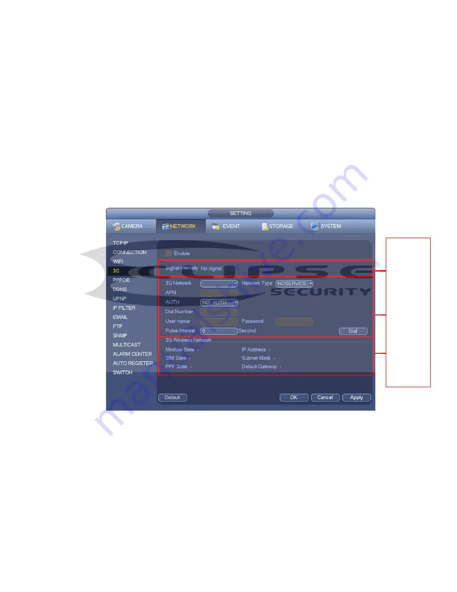
APN: It is the wireless connection server. It is to set you access the wireless network via which
method.
AUTH: It is the authentication mode. It supports PAP/CHAP.
Dial number: Please input 3G network dialup number you got from your ISP.
User name: It is the user name for you to login the 3G network.
Password: It is the password for you to login the 3G network.
Pulse interval: You can set dialup duration. Once you disable the extra stream, the connection time
begins. For example, if you input 5 seconds here, then 3G network connection period is 5 seconds.
The device automatically disconnect when time is up. If there is no extra stream, 3G network
connection is valid all the time.
If the alive time is 0, then the 3G network connection is valid all
the time.
Dial: Here you can enable or disable 3G network connection/disconnection manually.
3G wireless network: Here is to display wireless network status, SIM card status, dial status. If the 3G
connection is OK, then you can see the device IP address the wireless network automatically
allocates.
Figure 4-96
4.11.1.4 PPPoE
PPPoE interface is shown as in Figure 4-97.
Input “PPPoE name” and “PPPoE password” you get from your ISP (Internet service provider).
Click save button, you need to restart to activate your configuration.
After rebooting, NVR will connect to internet automatically. The IP in the PPPoE is the NVR dynamic
value. You can access this IP to visit the unit.
1
2
3
Содержание ECL-NVR16P-DH
Страница 1: ...ECL NVR16P DH User s Manual V 1 3 0 Our units do not support PAL...
Страница 11: ...x Accessories Check the following accessories after opening the box Please refer to the packing list in the box...
Страница 81: ...140 Figure 4 74 Figure 4 75...
Страница 82: ...141 Figure 4 76 Figure 4 77...
Страница 88: ...147 Figure 4 82 Figure 4 83...
Страница 89: ...148 Figure 4 84 Figure 4 85...
Страница 90: ...149 Figure 4 86 Figure 4 87...
Страница 92: ...151 Figure 4 89 Figure 4 90...
Страница 95: ...154 Figure 4 92 Figure 4 93 4 11 1 1 Connection The connection setup interface is shown as in Figure 4 94...
Страница 115: ...174 Figure 4 116 In Figure 4 116 click one HDD item the S M A R T interface is shown as in Figure 4 117 Figure 4 117...
Страница 130: ...189 Figure 4 136 Figure 4 137 4 14 3 1 Add Modify Group...
Страница 171: ...230 Figure 5 53 Figure 5 54...
Страница 172: ...231 Figure 5 55 Figure 5 56 Figure 5 57...
Страница 176: ...235 Figure 5 61 Figure 5 62...


