


111
Call Scan
In Figure 4-34, input Scan value and then click
to call a tour. Click again
to stop call.
Rotate
In Figure 4-34, click
to enable the camera to rotate.
System supports preset, tour, pattern, scan, rotate, light and etc function.
Note:
Preset, tour and pattern all need the value to be the control parameters. You can define it as y ou
require.
You need to refer to your camera user’s manual for Aux definition. In some cases, it can be used for
special process.
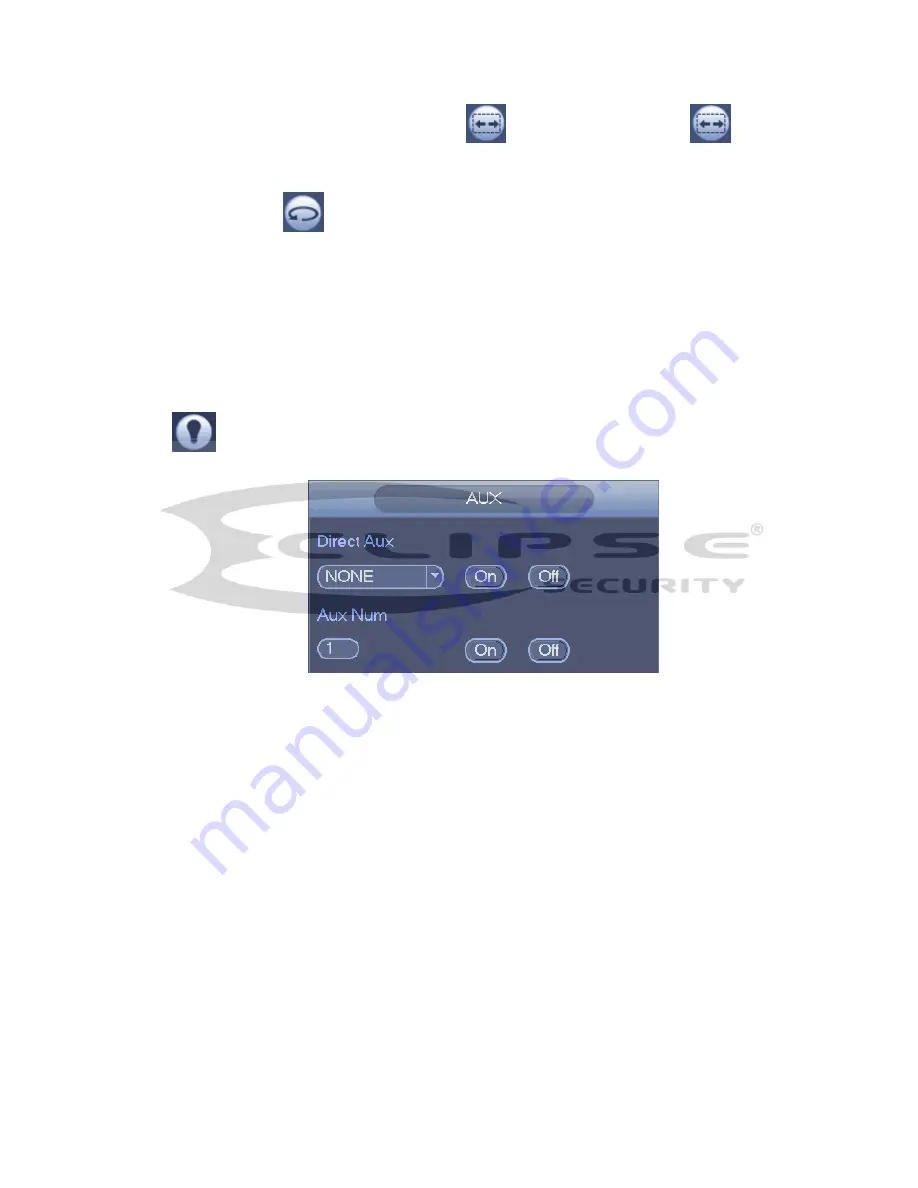
Aux
Click
, system goes to the following interface. The options here are defined by the protocol. The aux
number is corresponding to the aux on-off button of the decoder. See Figure 4-40.
Figure 4-40
4.7 Record and Snapshot
The record/snapshot priority is: Alarm->Motion detect->Schedule.
4.7.1
Encode
4.7.1.1 Encode
Encode setting is to set IPC encode mode, resolution, bit stream type and etc
From Main menu->Setting->System->Encode, you can see the following interface. See Figure 4-41.
Channel: Select the channel you want.
Type: Please select from the dropdown list. There are three options: regular/motion detect/alarm.
You can set the various encode parameters for different record types.
Compression: System supports H.264, MPEG4, MJPEG and etc.
Resolution: The
mainstream resolution type is IPC’s encoding config. Generally there is
D1/720P/1080P.
Frame rate: It ranges from 1f/s to 25f/s in NTSC mode and 1f/s to 30f/s in mode.
Bit rate type: System supports two types: CBR and VBR. In VBR mode, you can set vi deo quality.
Содержание ECL-NVR16P-DH
Страница 1: ...ECL NVR16P DH User s Manual V 1 3 0 Our units do not support PAL...
Страница 11: ...x Accessories Check the following accessories after opening the box Please refer to the packing list in the box...
Страница 81: ...140 Figure 4 74 Figure 4 75...
Страница 82: ...141 Figure 4 76 Figure 4 77...
Страница 88: ...147 Figure 4 82 Figure 4 83...
Страница 89: ...148 Figure 4 84 Figure 4 85...
Страница 90: ...149 Figure 4 86 Figure 4 87...
Страница 92: ...151 Figure 4 89 Figure 4 90...
Страница 95: ...154 Figure 4 92 Figure 4 93 4 11 1 1 Connection The connection setup interface is shown as in Figure 4 94...
Страница 115: ...174 Figure 4 116 In Figure 4 116 click one HDD item the S M A R T interface is shown as in Figure 4 117 Figure 4 117...
Страница 130: ...189 Figure 4 136 Figure 4 137 4 14 3 1 Add Modify Group...
Страница 171: ...230 Figure 5 53 Figure 5 54...
Страница 172: ...231 Figure 5 55 Figure 5 56 Figure 5 57...
Страница 176: ...235 Figure 5 61 Figure 5 62...


