13
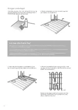
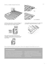
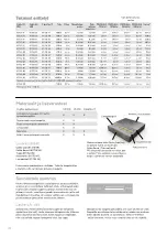
3. The spiral tube and the pipe are placed next to each other
in a recess in the wall.
If necessary, a recess for the spiral tube is made in the floor
between two heating cables, ending 30 – 60 cm from the
wall. The joint between the heating and connecting cable
should be embedded and must not be laid in the wall or in a
conduit, nor should it be bent. The nearest bend must be at
least 10 cm from the joint (see picture).
Location of sensor and connection cables
1a. Cable Kit includes a spiral tube with sealed ends.
The thermostat's sensor cable
is inserted in the spiral tube.
2a. The underfloor heating cable has a 2.5-metre
connection cable. It is run in a VP tube/plastic tube
designed for electrical materials (not included).
30-60 cm
2b. The joint for the connection cable and termination
may not be placed in or adjoining any shower spaces/
floor drains.
For supplementary kits, both cold cables
must be run up and connected in parallel in the thermo-
stat.
min.
10 cm
min.
10 cm
1b. The sensor cable's termination may not be cov-
ered by carpets or furnishings.
Program
06:45
Just nu
Om 0:15
23
19
Installation
M
Ω
/
Ω
1. The reel bracket simplifies work. Place the reel bracket in the
perforated hole under the bottom of the package. Lift the reel
onto the reel bracket and place a weight on the package cover.
When you pull the cable, the reel will now revolve.
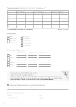
2. Perform the first insulation and resistance
measurement of the cable. Fill in the test
report or use Garantera on your smartphone.
EN


