16
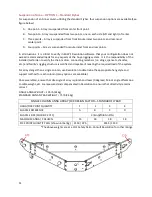
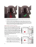
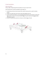
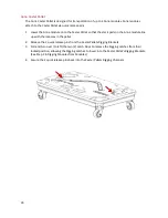
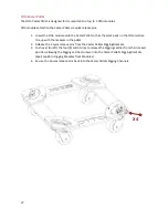
5. On the Caster Pallet, remove the four quick-release pins linking it to the bottom module,
releasing the stack from the Caster Pallet.
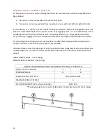
6. Verify that the bottom module’s Rigging Latches are fully retracted and inspect the entire
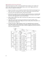
array. When an array is properly and safely flown, the ONLY orange that should be visible will
be on the Latches of on the bottom-most module. ANY OTHER VISIBLE ORANGE ON THE ARRAY
INDICATES A PROBLEM AND MUST BE ADDRESSED BEFORE CONTINUING. Once this inspection
is complete, fly out to trim height (if a complete array). (Fig. 4)
Rigging Modules from Modules (Anya/Anna)
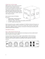
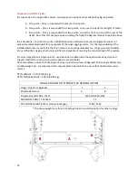
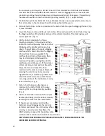
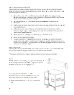
Each Anya module contains its own rigging support structure,
based on the simple and safe Rigging Latch-and-pin design.
Two grips on each side of the Power Plant control the rigging
elements. The upper Pin Grip drives the Rigging Pins in and
out while the lower Latch Grip moves the Rigging Latches up
and down. IT IS CRITICAL THAT USERS OPERATE THE CORRECT
GRIP WHEN ASSEMBLING AN ARRAY. NEVER OPERATE BOTH
GRIPS ON THE SAME SIDE OF THE SAME MODULE. PROPER
ASSEMBLY REQUIRES OPERATION OF THE LATCH GRIP OF THE
UPPER MODULE AND THE PIN GRIP OF THE
LOWER MODULE.
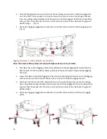
To attach a module to another (within a column):
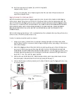
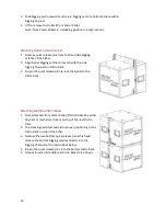
1. Using a chain motor, hoist the first 1-4 modules
including the Flybar off of the Caster Pallet. User will
likely find this a convenient time to begin cabling the
array, depending on the location of the Distro Rack(s).
2. Retract the Rigging Latches of the bottom Anya
module by pulling on the Latch Grips (one per side of
Содержание ADAPTive systems
Страница 1: ...Accessory Rigging Guide...

