Tripp Lite by Eaton SmartPro Advanced User Guide 614-40195—Rev 01
23
44..55
C
Coom
mm
muunniiccaattiioonn P
Poorrttss
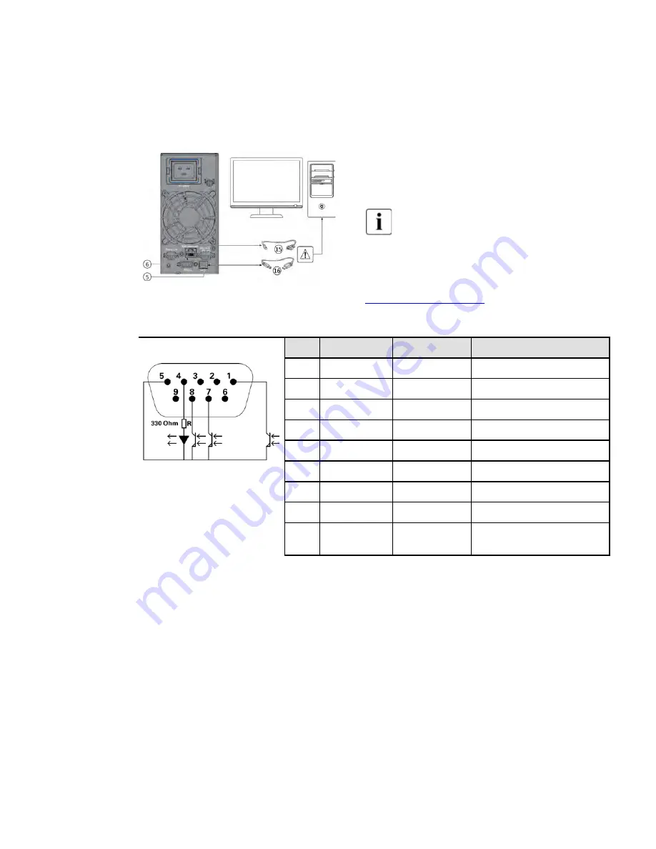
Table 17. RS232/USB Communication Port Connection Steps
1.
Connect the RS232 (15) or USB (16) communication cable to the
serial or USB port on the computer equipment.
2.
Connect the other end of the communication cable (15) or (16) to
the USB (5) or RS232 (6) communication port on the UPS.
The UPS can now communicate with Eaton Tripp Lite Series
power management software.
You can improve the remote monitoring and power management of
the UPS by adding a communication card compatible with the
SmartPro product, see paragraph
.
Table 18. RS232 Communication Port Contact Details
Pin
Signal
Direction
Function
Contact characteristics (optocoupler)
• Voltage: 48 V DC max
• Current: 25 mA max
• Power: 1.2 W
1
Bat low
Output
Low Battery Output
2
TxD
Output
Transmit to external device
3
RxD
Input
Receive from external device
4
I/P SIG
Input
-
5
GNDS
-
Signal Common tied to chassis
6
PNP
Input
Plug and Play
7
UPS OK
Output
UPS OK
8
BAT mode
Output
UPS on battery mode
9
+5V
Output
Power supply for external signal or
options
Содержание Tripp Lite SmartPro Series
Страница 6: ......
Страница 10: ...x Tripp Lite by Eaton SmartPro Advanced User Guide 614 40195 Rev 01 List of Figures...
Страница 12: ...xii Tripp Lite by Eaton SmartPro Advanced User Guide 614 40195 Rev 01 List of Tables...
Страница 16: ...4 Tripp Lite by Eaton SmartPro Advanced User Guide 614 40195 Rev 01 Introduction...
Страница 28: ...16 Tripp Lite by Eaton SmartPro Advanced User Guide 614 40195 Rev 01 Installation...
Страница 44: ...32 Tripp Lite by Eaton SmartPro Advanced User Guide 614 40195 Rev 01 Operation...
Страница 58: ...614 4019501 614 40195 01...


