manualshive.com logo in svg
background image

3

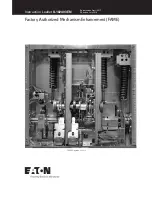
Instruction Leaflet

 IL01301060E

Effective June 2016

Series NRX drawout and breaker 

three-way cable interlock installation

and removal instructions

EATON 

www.eaton.com

Section 2: Installation of three-way cable  
interlock

Proceed with the following 9 steps.

Step 1e: 

Remove the four screws (six for 4-pole breaker) holding the 

cover in place.  Pull down on the charging handle and remove the front 

cover.

Step 2e: 

Remove the three screws holding the levering device side 

plate then remove the levering device side plates.

Figure 2. Steps 1 and 2.

Step 3e: 

Install the drive arm (E) to the end of the pole shaft using an 

M6 x 30 mm flat-head screw (F).  The drive arm should be oriented as 

shown. Torque to 65-85 in.-lbs (7.3 - 9.6 N•m).

Step 4e: 

Install the trip pin (A) to the trip arm using an M3 x 16 mm flat-

head screw (B).  Use a wrench to hold the trip lever during installation. 

Torque to 3-5 in.-lbs (0.3 - 0.6 N•m).  Replace Lev-in side plate (Figures 

3 and 4).

Figure 3. Steps 3 and 4.

(A) Trip pin

(E) Drive 

arm

Figure 4. Steps 4.

Step 5e: 

Fasten the interlock assembly (J) to the drawout cassette’s 

right-side sheet using four M6 x 12 mm hex bolts (C) and four lock 

washers (D).  Torque to 40 - 50 in.-lbs (4.5 - 5.6 N•m).

Figure 5. Step 5.

Step 6e:  

For type 32 and 33 interlock kits, fasten four cable brackets 

(G) to the drawout cassette’s right-side sheet just below the interlock 

assembly (mounted in Step 5) using two M6 x 10 mm thread-forming 

screws (H).  Torque to 65 - 85 in.-lbs (7.3 - 9.6 N•m) (refer to Figure 8 

for the correct configuration of type 31 interlock kits).

Align as shown

(C) and (D)

Содержание Series NRX

Страница 1: ...FLET COULD RESULT IN DEATH BODILY INJURY OR PROPERTY DAMAGE m WARNING THE INSTRUCTIONS CONTAINED IN THIS IL AND ON PRODUCT LABELS HAVE TO BE FOLLOWED OBSERVE THE FIVE SAFETY RULES DISCONNECTING ENSURE...

Страница 2: ...ion of the breakers and are available in 5 6 8 and 10 foot lengths 1 5 1 8 2 4 and 3 0 m Individual cable kits are ordered separately Required tools 10 mm socket drive socket 11 16 inch open end wrenc...

Страница 3: ...nted as shown Torque to 65 85 in lbs 7 3 9 6 N m Step 4 Install the trip pin A to the trip arm using an M3 x 16 mm flat head screw B Use a wrench to hold the trip lever during installation Torque to 3...

Страница 4: ...E 8 SHOWS THE TYPICAL CABLE ROUTING FOR BOTH TYPES 31 AND 33 INTERLOCKS AND FIGURE 9 SHOWS THE TYPICAL ROUTING FOR TYPE 32 INTERLOCKS THE CABLE MOUNTING ON THE DRIVE SIDE IS THE SAME FOR ALL TYPES MOU...

Страница 5: ...f bulkhead fitting enters slotted hole in cable bracket threads show above bracket 7 Bring bulkhead washer and nut down to threads and hand tighten 8 Adjust two bulkhead nuts to approximately center b...

Страница 6: ...el fitting Lower nuts Rubber boot Outer bulkhead nut Bulkhead nut Driven end cable bracket Swivel fitting Driven end long rod Lower nuts Driven end cable bracket Figure 15 Step 10 Step 11 This step de...

Страница 7: ...justments on driven long rod end of cable refer to Figure 15 As adjustments are made with the connected breakers in different states of OPEN and CLOSED make certain that gaps between the swivel fittin...

Страница 8: ...mpt 2 CLOSE Breaker C verify Breaker A remains CLOSED Again verify Breaker B will not respond to CLOSE attempt 3 OPEN Breaker A verify Breaker B will not respond to CLOSE attempt 4 OPEN Breaker C all...

Страница 9: ...9 Instruction Leaflet IL01301060E Effective June 2016 Series NRX drawout and breaker three way cable interlock installation and removal instructions EATON www eaton com Notes...

Страница 10: ...riate Eaton selling policies or other contractual agreement between Eaton and the purchaser THERE ARE NO UNDERSTANDINGS AGREEMENTS WARRANTIES EXPRESSED OR IMPLIED INCLUDING WARRANTIES OF FITNESS FOR A...

Отзывы: