background image

3

Technical Data 

TD150029EN

Effective November 2020

PXM4/6/8K meter color touchscreen

display quick start guide

EATON www.eaton.com

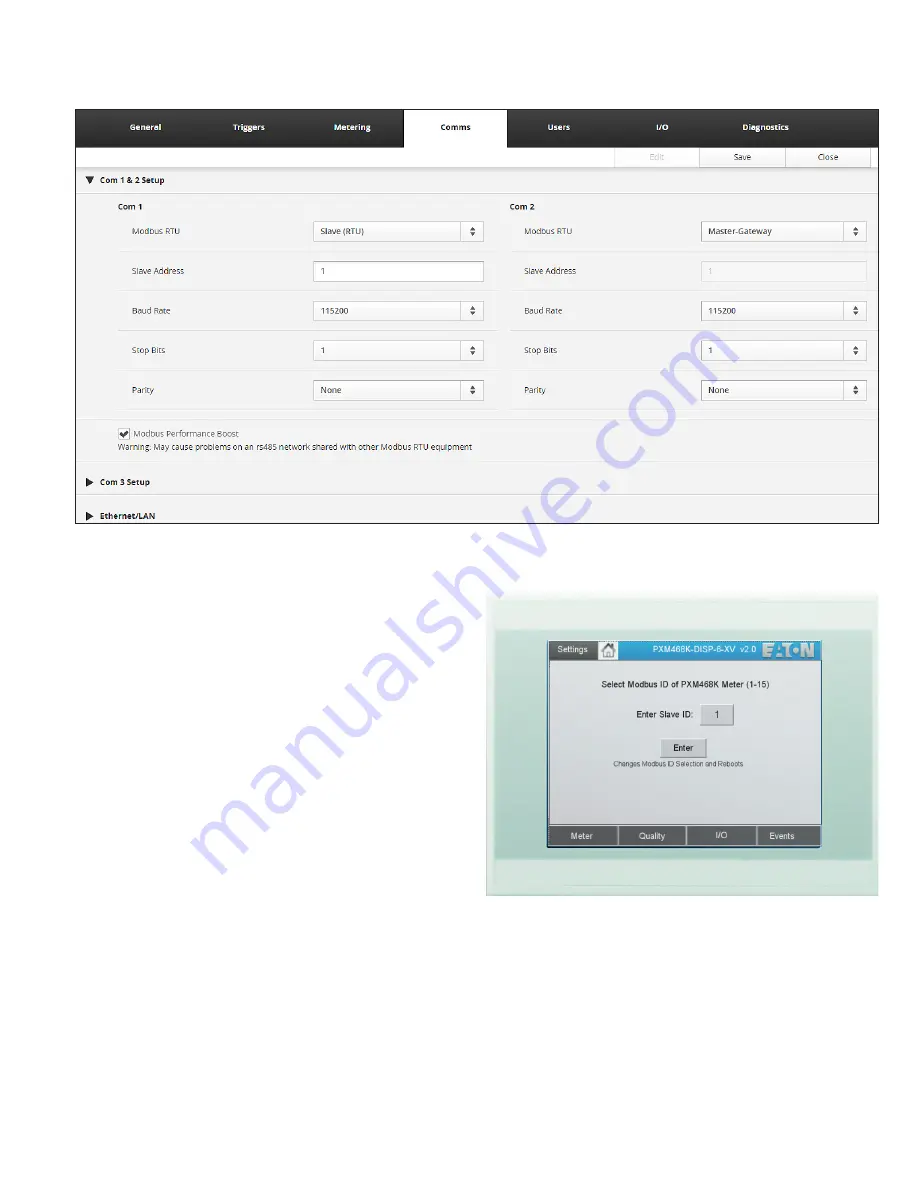
Figure 6. Meter web server configuration screen COM 1 & 2 setup.

Connections

To use the PXM4/6/8K meter color touchscreen display, provide  

24 Vdc and connect the power cable between the color touchscreen 

display and the PXM4/6/8K meter.
The display’s plug-in terminals provide connections for +24, GND 

and common (0).
Included with the PXM4/6/8K meter color touchscreen display is a 

data cable to connect the DB9 of the color touchscreen display to 

3-terminal COM 1 (RS485) of the PXM4/6/8K meter.
The supplied cables are designed to connect the meter to the 

PXM4/6/8K meter color touchscreen display as follows:

• 

Data cable: CM3

• 

Power cable: CM4

In order to communicate with the display, the meter must be config-

ured as “Slave (RTU).”  This can be set using the meter’s web server 

configuration page for COM 1 & 2.
For best results, use the default communication settings for the  

PXM4/6/8K meter and PXM4/6/8K meter color touchscreen display 

(115.2 kbps, 1 start bit, 1 stop bit, no parity).

ote: 

N

By default, the PXM4/6/8K meter color touchscreen display is pre-

set for a PXM4/6/8K meter Modbus address of “01”.  To accommodate a 

different Modbus address, the user MUST change the PXM4/6/8K meter 

color touchscreen display’s “Modbus ID”.  This number MUST match the 

rotary switch located on the side of the meter. This setting can be found 

under Settings > Meter ID.

Figure 7. Changing the Modbus ID.

Содержание PXM4/6/8K

Страница 1: ...wer 24 Vdc input Recommended PXM display power cable 67A2180H11 between the display and PXM4 6 8K s CM3 source Optional PSG60E 85 264Vac PSG60F 320 576Vac Effective November 2020 Supersedes June 2019 Technical Data TD150029EN PXM4 6 8K meter color touchscreen display quick start guide Display measurements Height 5 24 in 133 mm Width 6 81 in 173 mm Depth 1 54 in 39 mm Weight 1 32 lb 600 g Cutout di...

Страница 2: ...rds the wider ends of the retaining brackets Clip on the retaining brackets in the recesses provided for them on the device Figure 4 Mounting the PXM4 6 8K meter display 7 Check for proper alignment of the PXM4 6 8K meter color touch screen display Then fix the device by torquing the threaded pins to 0 1 Nm 0 86 lb in with a 2 mm hexagonal screwdriver The front of the display should be flush with ...

Страница 3: ...esigned to connect the meter to the PXM4 6 8K meter color touchscreen display as follows Data cable CM3 Power cable CM4 In order to communicate with the display the meter must be config ured as Slave RTU This can be set using the meter s web server configuration page for COM 1 2 For best results use the default communication settings for the PXM4 6 8K meter and PXM4 6 8K meter color touchscreen di...

Страница 4: ... application 3 On the display select Start Settings Network and Dial up Connections Double click ONBOA to see the Display s Ethernet connection IP address Verify that this is 192 168 1 1 If it is not edit the fields and click OK 4 Attach Ethernet cable between the display and PC 5 Set the PC s Ethernet address to be compatible with the display e g 192 168 1 99 6 On the PC use Windows File Explorer...

Страница 5: ...5 Technical Data TD150029EN Effective November 2020 PXM4 6 8K meter color touchscreen display quick start guide EATON www eaton com Notes ...

Страница 6: ... con tractual agreement between Eaton and the purchaser THERE ARE NO UNDERSTANDINGS AGREEMENTS WARRANTIES EXPRESSED OR IMPLIED INCLUDING WARRANTIES OF FITNESS FOR A PARTICULAR PURPOSE OR MERCHANTABILITY OTHER THAN THOSE SPECIFICALLY SET OUT IN ANY EXISTING CONTRACT BETWEEN THE PARTIES ANY SUCH CONTRACT STATES THE ENTIRE OBLIGATION OF EATON THE CONTENTS OF THIS DOCUMENT SHALL NOT BECOME PART OF OR ...

Отзывы: