4
Technical Data
TD150029EN
Effective November 2020
PXM4/6/8K meter color touchscreen
display quick start guide
EATON www.eaton.com
Firmware updates
Eaton periodically releases firmware updates with feature enhance-
ments and stability improvements.
To update the firmware on the display, one of the following two
methods can be used:
USB drive, keyboard and mouse
1. Download the firmware update file from eaton.com\meters.
Save to a flash drive and unzip the folder.
2. Press the CTRL button on the right side of the display to exit the
application.
3. Under the display’s MyDevice, copy the UsbStorage\
InternalStorage folder (Edit > Copy).
4. Again, under MyDevice, delete the existing InternalStorage (File
> Delete).
5. Paste the new InternalStorage (Edit > Paste). This transfers the
firmware from the flashdrive to the display. Expect the transfer
to take 2 minutes. For files that already exist, select “Yes to All”
so that they are overwritten.
6. Power cycle the display.
7. On boot-up, enter the 7-character authentication code that is
printed on a label on the back of the display (see Figure 9). Click
Return. The authentication box will turn from red to green.
8. Click Save.
9. Double-click the GRS-CE5 to start the application (or, alternatively,
cycle power the display).
PC and ethernet cable
1. Download the firmware update file from eaton.com. Save to the
PC. Unzip the folder.
2. Press the CTRL button on the right side of the display to exit the
application.
3. On the display, select Start > Settings > Network and Dial-up
Connections. Double-click “ONBOA…” to see the Display’s
Ethernet connection IP address. Verify that this is 192.168.1.1. If
it is not, edit the fields and click OK.
4. Attach Ethernet cable between the display and PC.
5. Set the PC’s Ethernet address to be compatible with the display
(e.g. 192.168.1.99).
6. On the PC, use Windows File Explorer navigate to the down-
loaded firmware upgrade files so that the InternalStorage folder
appears.
Figure 7. Internal storage.
7. Open another instance of Windows File Explorer address bar,
type “ftp://192.168.1.1“ (or the display’s Ethernet connection IP
address from step 3). This will show the file structure in the dis-
play.
Figure 8. Example with display set for 192.168.1.98 and PC set
for 192.168.1.99.
8. All firmware goes into the InternalStorage folder.
9. Delete the existing InternalStorage folder (OS and runtime fold-
ers are likely protected).
10. With a mouse, drag the InternalStorage folder from the firm-
ware update (step 6) to the FTP pane. Expect the transfer to
take 2 minutes. For files that already exist, select “Yes to All”
so that they are overwritten.
11. Power cycle the display.
12. Enter the 7-character authentication code that is printed on a
label on the back of the display (see Figure 9). Click Return. The
authentication box will turn from red to green.
13. Click Save.
14. Double-click the GRS-CE5 to start the application (or, alterna-
tively, cycle power the display).
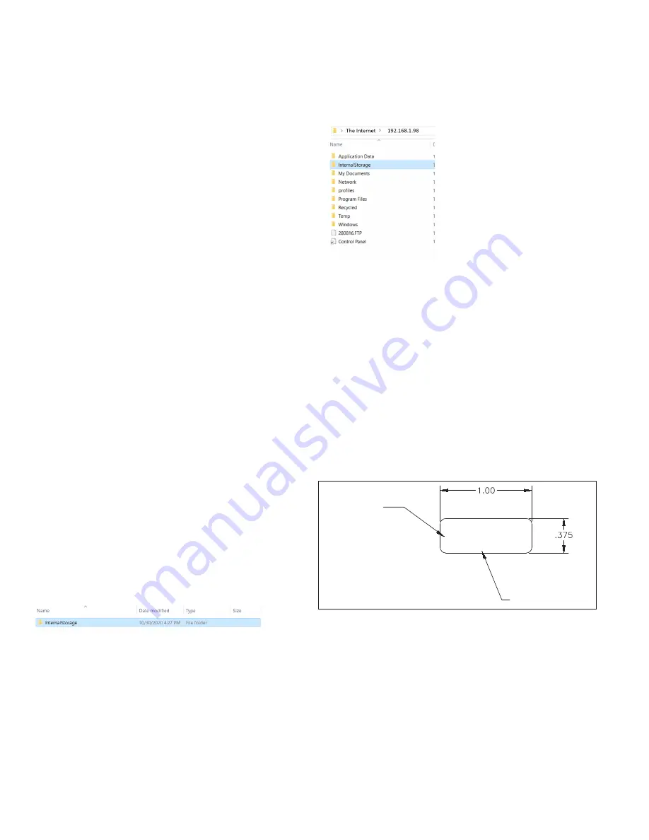
Figure 9. Example authorization code label on rear of display.
Serial number:
10140011462
Auth: 7138063
Serial number
from rear
of display
Authorization code


