Eaton PW9340-80I-N Скачать руководство пользователя страница 26

80 kVA - 130 kVA UPS

User’s and Installation Manual

1017397

Revision D (update)

26

6.4 Inputs

The UPS communication device includes four inputs (terminal block 2: 1-2, 3-4, 5-6, 7-
8) for building alarms. These inputs can be for example informing when UPS gets
power from generator, shutting down and starting up inverter remotely or turning to
bypass mode remotely. These inputs can be activated by connecting the two pins
together of the particular terminal.
These inputs have the following values:

Generator On Input TB2:1,2

The generator on input is used for inhibiting the transfer to static bypass line when the
UPS is supplied by an unstable ac source.
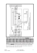
The generator auxiliary contact wires are connected on terminal block 2: 1,2 (see figure
11). In normal operations the  terminals 1 and 2 are not be connected together. When
these pins are connected together by floating contacts of the generator control device,
the logic circuitry in the UPS will prevent the transfer to unstable power source. When
the unit is delivered the connection on terminals 1 and 2 will be open.

Remote Output On/Off Input TB2: 3, 4

The remote output on/off input is used to turn off the output of the UPS from a distance.
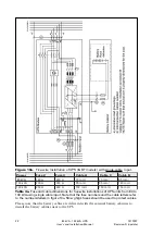
Remote output on/off wires are connected on terminals 3 and 4 (see figure 11).
The terminals 3 and 4 are not to be connected together in normal operation. When the
pins are connected together by floating contact the inverter will be turned off and also the
static bypass line will be turned off. In order to turn on the inverter and the static bypass
line the connection between these pins have to be opened.

External Bypass Switch Input TB2: 5, 6

If the UPS system is equipped with an external bypass switch, its status can be monitored
by the UPS via terminals 5 and 6. The external bypass switch auxiliary contact wires are
connected on terminals 5 and 6 (see figure 11). For normal UPS operation the connection
shall be open as default. If an external bypass switch will be used, contact your dealer first.

Environment Alarm Input TB2: 7, 8

The environment alarm input is used for connecting the UPS to your building alarms,
such as overtemperature or smoke detector alarms.
The environment alarm input contact wires are connected on terminals 7 and 8 (see
figure 11). When this alarm is activated it will be indicated to the user through RS232
ports. When connection in terminals 7,8 is open, the alarm is inactive as default.

Note!

The programmable auxiliary inputs (Generator ON, External Bypass Switch, Remote Output
On/Off, Environment Alarm) must not be galvanically connected to any mains connected
circuits. Reinforced insulation to the mains is required for equipments and cables connected
to these connections.

Note!

The programmable auxiliary inputs are NOT galvanically isolated from each other. Use
dry contacts.

6.5 X-Slot Modules

Optional X-Slot modules allow the UPS to communicate in a variety of networking
environments and with different types of devices. The Powerware 9340 is compatible
with any X-slot module, including:

RS232 Module - has one serial communication port.

Modbus/Jbus Module - connects to an industrial automation system

AS400 Relay Module - provides additional relay outputs

SNMP/Web Module - has a flexible SNMP/Web communication port.

Modem Module - provides modem functions for remote monitoring

Содержание PW9340-80I-N

Страница 1: ...80 130 kVA single and parallel UPS Systems User s and Installation Manual...

Страница 2: ......

Страница 3: ...Power connections 16 6 Computer and alarm connections 24 6 1 Connecting the UPS to a computer 24 6 2 Potential free relay outputs 25 6 3 Emergency Power Off Input EPO 25 6 4 Inputs 26 6 5 X Slot Modul...

Страница 4: ...her and may not be reproduced even extracts unless permission granted Every care has been taken to ensure the accuracy of the information contained in this manual but no liability can be accepted for...

Страница 5: ...lectrical interference Interference from outside the facility such as lightning power company accidents and radio transmissions and interference from inside the facility from motors air conditioners v...

Страница 6: ...load The static bypass switch transfers automaticly the load to the bypass line when the inverter is overloaded or the inverter is not able to feed the load Maintenance bypass switch is used to bypass...

Страница 7: ...eed any charging Hence the function of ABM system is to prolong the battery life up to 50 on average It also monitors that the load never crashes because of bad or defected battery The key to long bat...

Страница 8: ...d in this patented design It provides automatic load sharing and module level redundancy with nothing other than the power connecting the Hot Sync version of UPS modules 2 2 UPS configurations The UPS...

Страница 9: ...abinets and racks External bypass switch cabinets External bypass isolation transformers External SPM9340 system parallel cabinet for parallel UPS systems Remote and multilingual ViewUPS display panel...

Страница 10: ...hem may prove fatal All operations inside the cabinets must be carried out only by a service engineer from the manufacturer or from an agent authorised by the manufacturer 3 3 User operations The only...

Страница 11: ...ng materials should be stored for further investigation If the damage is visible a claim for shipping damage must be filed immediately Note Check the shock tilt indicator To file a claim for shipping...

Страница 12: ...and the battery options the following points have to be remembered Avoid temperature and humidity extremes To maximise the life time of the batteries an ambient temperature of 15 C to 25 C is recomme...

Страница 13: ...made from metal must be either connected to the protective conductor or insulated from the battery and the place of installation EN 50272 2 5 2 Floor loading When planning the installation the floor...

Страница 14: ...X1 in first battery cabinet in string or to battery cabinet indicated as Cabinet 1 After this select Add New Temp Sensor from LCD display and press Select to verify new sensor The sensor will be iden...

Страница 15: ...80 kVA 130 kVA UPS User s and Installation Manual 1017397 Revision D update 15 Figure 6a Connecting battery cabinets 80 130 kVA UPS Figure 6b Connecting temperature sensors for the battery cabinets...

Страница 16: ...phase and connection for rectifier input also in IGBT model a non functional termination point for the neutral wire if provided 3 phase and N and connection for bypass input 3 phase and N and PE conn...

Страница 17: ...80 kVA 130 kVA UPS User s and Installation Manual 1017397 Revision D update 17 Figure 8a Location of switches and terminals...

Страница 18: ...er bar 25 3mm Bolt M10 17 mm Hex Socket Neutral Bolt M10 17 mm Hex Socket Ground Flat copper bar 30 5mm Bolt M8 13 mm Hex Socket Battery Input Terminal 32 mm Bolt M10 8 mm Hex Allen Keys with fatening...

Страница 19: ...trical connections to the installation site have been properly executed Also check fuse or circuit breaker ratings and cable dimensions against tables 3 or 4 for 80 130 kVA systems The figure to follo...

Страница 20: ...to the numbers letters in figure 9a Slow gG gL fuses should be used to protect cables Please note that the battery cables delivered with the external battery cabinets are to install the external batt...

Страница 21: ...to the numbers letters in figure 9b Slow gG gL fuses should be used to protect cables Please note that the battery cables delivered with the external battery cabinets are to install the external batte...

Страница 22: ...m 0 5 1 m m 0 5 1 Figure 10a Five wire installation of UPS IGBT models with single cable input Table 4a Fuse and cable dimensions for five wire installations of UPS units from 80 to 130 kVA using sing...

Страница 23: ...m 0 5 1 m m 0 5 1 Figure 10b Five wire installation of UPS SCR models with single cable input Table 4b Fuse and cable dimensions for five wire installations of UPS units from 80 to 130 kVA using sing...

Страница 24: ...arate from any power cables 6 1 Connecting the UPS to a computer The UPS is delivered as a complete solution package with accompanying Software Suite To connect the UPS to the computer use the communi...

Страница 25: ...091 1 1 The relay contacts must not be galvanically connected to any mains connected circuits Reinforced insulation to the mains is required 6 3 Emergency Power Off Input EPO This input is used to shu...

Страница 26: ...connection between these pins have to be opened External Bypass Switch Input TB2 5 6 If the UPS system is equipped with an external bypass switch its status can be monitored by the UPS via terminals...

Страница 27: ...status of UPS operation with five LED indicators and with a LCD screen The display also generates audible alarm if the user should be alerted Figure 13 Control panel with the main screen LED indicato...

Страница 28: ...erformance meters for the system or critical load Setup Allows one to view contrast date time firmware versions system identity and parallel information Configuration of the UPS requires a password Th...

Страница 29: ...80 kVA 130 kVA UPS User s and Installation Manual 1017397 Revision D update 29...

Страница 30: ...and back to normal mode are controlled from this screen by pressing the Bypass and Normal pushbuttons As safety feature the UPS can be locked to bypass mode via software and alarm will be given To re...

Страница 31: ...rned off and the maintenance bypass switch is in bypass position and F1 F2 opened the UPS is isolated from the input and output power lines MIDDLE this position is used only during transfer from maint...

Страница 32: ...this case the UPS will be in battery mode supplying power from the batteries or in the static bypass mode if the bypass line voltage and frequency are acceptable During the battery start up the UPS w...

Страница 33: ...igned to cope with a continuous load from the day it is installed until a change is needed in the backup battery bank Shutting down to Maintenance Bypass Go to System Control menu in LCD display see c...

Страница 34: ...D update 34 8 Parallel UPS System 8 1 Introduction Up to four UPS modules Hot Sync may be installed together in the parallel for Redundancy or Capacity system Figure 14 System wiring diagram of 1 4 pa...

Страница 35: ...ust be inside 10 tolerances and the same type Due to the same cabling impedance the equal cables mean equal load sharing for the static bypass mode Negligence of the instructions may cause the paralle...

Страница 36: ...0 6 2 I 0 3 1 0 4 3 9 W P x 2 A 7 7 3 m m 0 0 3 2 A 0 0 4 A V k 0 0 3 I 0 0 1 0 4 3 9 W P x 3 A 5 3 4 m m 0 5 1 x 2 2 A 0 0 5 A V k 0 0 3 I 0 0 1 0 4 3 9 W P x 3 A 5 3 4 m m 0 5 1 x 2 2 A 0 5 2 x 2 A...

Страница 37: ...s and CAN cable with resistors Note Pay attention to the signal polarity because pins 1 CANH and pin 2 CANL must not be interchanged between UPS modules The shield is connected to pin 3 COMMON on the...

Страница 38: ...n D update 38 Contact signal from the system bypass switch S51 Parallel UPS system for redundancy or capacity has normally an external make before break system bypass switch function installed as show...

Страница 39: ...tiates parallel UPS modules to gate static switch regardless of internal bypass condition or inverter synchronization 8 4 Starting up System Check that the power and control wiring has been done corre...

Страница 40: ...e UPS module for service In the capacity mode the external system bypass switch S51 must be first used to transfer the system load to external bypass power refer to SPM9340 design with local tie panel...

Страница 41: ...the outputs of parallel UPS modules Powerware s optional system bypass module SPM9340 is a ready made solution for the maximum system of four parallel UPS modules It includes four service disconnect...

Страница 42: ...ed by a manufacturer Battery maintenance The condition of the batteries is crucial to correct operation of the UPS The UPS units are provided with the automatic battery test which continuously monitor...

Страница 43: ...voltage and frequency independent operation 1 4 Efficiency 92 at nominal load 90 at half load 1 5 Standards Performance ENV50091 3 IEC 62040 3 Safety EN50091 1 1 IEC 60950 EMC EN50091 2 1 6 Conformit...

Страница 44: ...0 kVA at PF 0 8 4 2 Nominal voltage 220 380 230 400 240 415 50 60 Hz 4 3 Crest factor 3 1 computer and server loads 4 4 Linear loads 0 8 lagging to 0 9 leading 4 5 Voltage regulation 1 at static 5 at...

Страница 45: ...ery Management or traditional float charging 6 3 Nominal battery voltage 384 VDC 192 cells 6 4 DC bus reference in float mode 2 31VPC 10 25 C 2 26VPC 50 C 6 5 Battery cut off voltage 1 7 VPC voltage p...

Страница 46: ...R H 2 1 2 3 x 3 k c a R 5 7 2 3 L 4 6 3 7 1 x 5 1 7 x 0 0 7 2 7 2 2 0 1 1 6 6 7 5 6 4 1 4 5 3 4 3 0 3 7 2 0 5 3 R H 2 1 2 3 x 3 k c a R 5 0 3 3 L 4 3 4 7 1 x 5 1 7 x 0 0 0 3 8 7 2 7 3 1 5 8 7 6 6 5 0...

Отзывы: