Eaton Profile Скачать руководство пользователя страница 56

56

Profile

Installation Manual

PROFILE INSTALLATION MANUAL

         Eaton.com/profile

P a g e


54


Eaton’s Profile Command Console 
Installation Manual


B.


To install A Linear Sit-to-stand Desk 

(Refer to the previous section, Section IV.A., for corner sit-to-stand desks) 

 
All Profile linear sit-to-stand desks are comprised of similar components: lift leg assemblies, work surface support frames, work 
surfaces, electronic components and core skins.  Some linear sit-to-stand desks may have additional components such as manual 
counterbalance mechanisms (for non-motorized keyboard surfaces) and cable management devices.  However, while the 
components are all similar, there will be some variations based on the model size and configuration. 

Refer to the following table (figure 84) to determine the features and variations of your specific model number.  The installation 
steps on the following pages will refer to the information found in this table. 


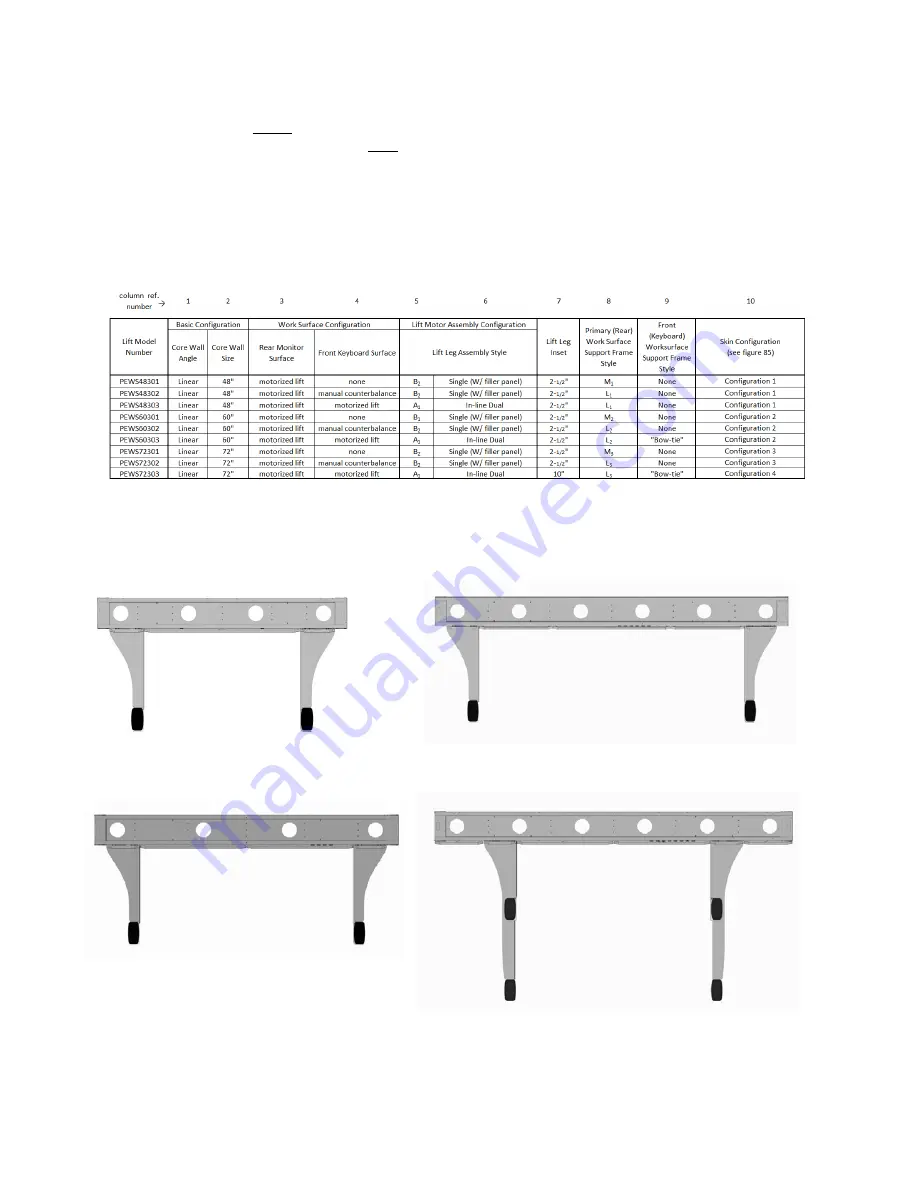
Step 1.  Determine The Component Layout Of Your Linear Sit-to-Stand Desk 

Refer to table 84 and figure 85 to determine the layout of your linear sit-to-stand desk model.  They will define the size and 
style of each component along with the locations of your core wall skins and lift leg assemblies.  The figures in step 2 and step 
5 on the following pages will help you visually identify the style and size of your lift leg and work surface frame components. 


Linear Sit-to-Stand Desk Configuration Table (Figure 84

)


Lift leg 

Ref col. 5 

Lift leg 

Ref col. 5 

Lift leg 

Ref col. 5 

Lift leg 

Ref col. 5 

Lift leg 

Ref col. 5 

Lift leg 

Ref col. 5 

Lift leg 

Ref col. 5 

Lift leg 

Ref col. 5 

14


15

/

16

” Sk

in


14


15

/

16

” Sk

in


29 

7

/

8

” Skin 

19 

3

/

8

” Skin 

20 

15

/

16

” Skin 

20 

15

/

16

” Skin 

19 

3

/

8

” Skin 

3

/

8

” Sk

in


3

/

8

” Sk

in


Skin Configuration 1 

PEWS48301 
PEWS48302 
PEWS48303 


Skin Configuration 2 

PEWS60301 
PEWS60302 
PEWS60303 


Skin Configuration 3 

PEWS72301 
PEWS72302 


23 

15

/

16

” Skin 

Skin Configuration 4 

PEWS72303 


Figure 85 – Linear Sit-to-Stand Skin Configuration


Содержание Profile

Страница 1: ...Command Console Profile Command Console Installation manual...

Страница 2: ...play wall cores 14 Join linear core configurations 13 Angular core connectors 14 Stabilizing the core wall support structure 21 Installing a docker 21 Installing a full depth upright 22 Installing a l...

Страница 3: ...OR IMPLIED INCLUDING WARRANTIES OF FITNESS FOR A PARTICULAR PURPOSE OR MERCHANTABILITY OTHER THAN THOSE SPECIFICALLY SET OUT IN ANY EXISTING CONTRACT BETWEEN THE PARTIES ANY SUCH CONTRACT STATES THE E...

Страница 4: ...h the warning symbols that appear throughout this manual Before You Begin Before installing Eaton s Profile Command Console it is recommended that you do the following DANGER DANGER indicates a hazard...

Страница 5: ...trols to the off position then remove plugs from outlets 11 WARNING Risk of Electric Shock Connect this furnishing to properly grounded outlets only See grounding instructions 12 To reduce risk of ele...

Страница 6: ...ft motor Motorized sit to stand front work surface capacity 100 lbs Monitor pole capacity 60 lbs each WARNING Do not apply loads that exceed the capacity of the console The applied load includes any i...

Страница 7: ...section III D Support leg Ref section III D Privacy screen Ref section III I Vertical end trim Ref section III H Top trim cap Ref section III G Top trim cap with privacy glass Ref section III G Confe...

Страница 8: ...s Profile Command Console Installation Manual Profile Motorized Sit to Stand Desks Refer to section IV of this manual Standard steel skin Outer lift leg assembly RH Rear monitor work surface Front key...

Страница 9: ...l vary in complexity However while all installations will require the most basic elements of the Profile line core wall structures stabilizing elements and work surfaces more complex installations wil...

Страница 10: ...rd base core is 29 high where the top of the base core is coincident with the top of a stationary fixed height work surface Stackable display wall cores are available in 12 and 16 heights They can be...

Страница 11: ...ins If desired standard and modular skins can be intermixed where one type is on the user side of the core and the other type is on the opposite non user service side i e back of the core To learn mor...

Страница 12: ...is outside of the angle convex side The outer vertical narrow panel will be full height The inner wide vertical panel will be full height and have 2 mounting holes for a work surface L bracket Availab...

Страница 13: ...0 X configuration 3 core 180 T configuration Double angled concave configuration Linear configuration work surface on one side TYPICAL CORE WALL CONFIGURATIONS To learn more about configuring profile...

Страница 14: ...set into each trapezoidal tab Also attach the center vertical support s using 2 10 x 3 8 Phillips head self tapping screws for each support Joining Linear Core Configurations Attach adjacent core unit...

Страница 15: ...late front and rear panels and a plastic top cap Work surfaces are on the concave side of this type of configuration Figure 9 TYPICAL STATIONARY 2 CORE 90 WEDGE CONNECTOR FOR WORK SURFACES ON THE CONC...

Страница 16: ...VE SIDE OF THE CONFIGURATION Slots in the bottom front panel required for stationary work surface support brackets Plastic top cap Tie plate Top plate Top front panel full height on ergonomic connecto...

Страница 17: ...plastic top cap Work surfaces are on the convex side of this type of connector Unlike the concave angular connectors the narrow rear vertical panel is one piece and un slotted The wide front panel is...

Страница 18: ...and 90 135 135 configurations Both Y connectors share a similar assembly method and similar components angular tie plates an angular top plate 3 front panels and a plastic top cap Figure 11 TYPICAL S...

Страница 19: ...sembly method and similar components tie plates a top plate a plastic top cap front panels and for the T style a rear panel not required for X style Plastic top cap Top plate 20 x 1 2 hex head self ta...

Страница 20: ...erent support components than stationary fixed height work surfaces So as such while the ergonomic connectors are similar to the stationary connectors they will not have any of the features required t...

Страница 21: ...sembly sequence Refer to your office plan layout to determine the location of your core wall stabilizing components To learn more about configuring Profile with the appropriate stabilizing components...

Страница 22: ...ture Stabilizing The Core Wall Structure With A Linear Transition Upright A linear transition upright assembles to the vertical members of two adjacent base core frames that are joined in a linear con...

Страница 23: ...pplications For concave applications the rear panel of the angular core connector must be removed to gain access to the transition upright mounting holes Re attach the rear panel after installation of...

Страница 24: ...k surfaces but with one or two mitered edges Each mitered edge abuts the mitered edge of an adjacent work surface when used on the concave side of an angular core configuration Convex Wedge Work Surfa...

Страница 25: ...self tapping screws See figure 26 L brackets are also used to support the narrow edge of a convex wedge work surface see figure 13 Tie Plates If the stationary work surface is adjacent to another sta...

Страница 26: ...e support bracket Typical stabilizing component End panel shown Support Leg L bracket 10 x Phillips head wood 3 screw Work surface support bracket 20 x hex head self tapping screw 1 Tie plate L bracke...

Страница 27: ...n user side of the core and on the user side below the work surface If modular skins are not specified for the user side of the core the user side of the core above the work surface will have full wid...

Страница 28: ...adjacent modular style skins using 2 20 x hex head self tapping screws and 1 10 x Phillips flat head self tapping screws for each divider Vertical dividers are only required for the base core they are...

Страница 29: ...non user side of the core hooking at the bottom and latching at the top Installing A Modular Slat Wall Panel To The User Side Of A Core Wall Attach the slat wall panel to the face of the core wall wit...

Страница 30: ...ips head machine screws wherever there is a pre installed threaded insert in the side panel Use 8 x Phillips head wood screws to attach parts to the edge of the side panels Depending on the size of yo...

Страница 31: ...ofile Installation Manual PROFILE INSTALLATION MANUAL Eaton com profile P a g e 29 Eaton s Profile Command Console Installation Manual Figure 37 10 x 3 8 Phillips head self tapping screws Retention cl...

Страница 32: ...nge combinations styles Each style is defined by the height of the cap s two vertical flanges 1 2 or 2 The core wall s skin configuration will dictate the top cap style Normally a core side configured...

Страница 33: ...female portion of each latch will be pre snapped onto the male portion for shipment Remove the female portions of the latches taking note of their orientation with respect to the male portions Snap t...

Страница 34: ...s head clamping screws on each bracket See figures 41 and 42 Attach the slotted base plate to the middle of the core wall s top channel with 6 20 x hex head self tapping screws Depending on your confi...

Страница 35: ...place tighten the 2 Phillips head clamping screws on each bracket See figure 44 60 and 72 sizes require 2 additional top cap support brackets at the center Locate each bracket 4 from the center of th...

Страница 36: ...that match the most common core wall heights Vertical end trim panels are also available to finish off the ends of core walls that transition from one height to another To Install A Vertical End Trim...

Страница 37: ...hex head self tapping screws see figure 48 Attach the end trim panel to the core with 20 x hex head self tapping screws see figure 49 Then attach the top plate to the privacy screen with 10 Phillips...

Страница 38: ...A CPU Caddy Attach the side plate to the base core with 4 20 x hex head self tapping screws Position the plate so that the bottom of the plate is 2 from the floor A final minor height adjustment may...

Страница 39: ...ront adjustable surface for keyboards The primary rear surface is always motorized however the secondary front surface may have either a motorized lift mechanism or a manually adjusted counterbalance...

Страница 40: ...nic components and core skins Some corner sit to stand desks may have additional components such as manual counterbalance mechanisms for non motorized keyboard surfaces and cable management devices Ho...

Страница 41: ...eg Assembly May not be required Refer to column 7 in table 53 Outer Lift Leg Assembly Style will vary Refer to column 6 in table 53 This skin may not be required Refer to column 11 in table 53 Skin Po...

Страница 42: ...dentify the appropriate lift legs for each of your sit to stand desks A B C Figure 56 A Style In Line Dual Outer Lift Legs LH Assembly Shown Figure 57 B Style Single Outer Lift Legs LH Assembly Shown...

Страница 43: ...ust be properly aligned and leveled Failure to properly align the walls can cause excessive stress on the desk s lift components resulting in poor performance and premature wear Before proceeding with...

Страница 44: ...rews as shown in figure 63 A 2 1 2 inset is shown in this example c Install 2 10 x 3 8 Phillips head self tapping screws into the top of the lift leg face plate Leave the screws protruding about 1 16...

Страница 45: ...E style center lift legs If your desk requires an F style center lift leg proceed to step 5b If your desk does not require a center lift leg at all proceed to step 6 b The upper and lower center lift...

Страница 46: ...er lift leg refer to step 5a If your desk does not require a center lift leg at all proceed to step 6 b Attach the F style center lift leg assembly to the center of the middle core wall with 4 20 x he...

Страница 47: ...f the lift motor The top of the strain relief should be flush with the top of the column See figure 68 The connectors for the outer rear lift motors should exit the motors towards the knee well of the...

Страница 48: ...one model to another Use figures 70 through 73 along with the information found in column 16 of table 53 to identify the appropriate work surface support frame for each of your sit to stand desks Figu...

Страница 49: ...to stand desk model Position the rear work surface support frame on top of the lift motor s aligning the correct holes with the lift motor s If you have difficulty in aligning the correct holes you ma...

Страница 50: ...N THE ASSEMBLY DO NOT OMIT ANY SCREWS Step 9a Install The Front Work Surface Support Brackets This step only applies to corner sit to stand desks with motorized front work surfaces refer to column 5 i...

Страница 51: ...pplies to corner sit to stand desks with motorized front work surfaces refer to column 5 in table 53 If your desk has a manually counterbalanced front work surface refer to step 11 to learn how to ins...

Страница 52: ...hers and locknuts provided with the mechanism Then assemble nut covers onto the lock nuts b Place the counterbalance mechanism on the floor Adjust the paddle and knobs until all four mounting brackets...

Страница 53: ...faces with 2 10 x 1 3 4 long Phillips head screws as shown in figure 81 The rear work surface control box mounts to the right hand work surface frame channel with its power receptacle pointing left to...

Страница 54: ...t lift motors PEC60602 However some desks will only have 2 rear lift motors and or a manual counterbalanced front work surface with no lift motors Note the lift motor numbers in figure 82 connect the...

Страница 55: ...and holding the down button The motors will automatically lower to their bottom most position if not already there then run upwards approx 3mm and then down again to their lowest position Only release...

Страница 56: ...ges will refer to the information found in this table Step 1 Determine The Component Layout Of Your Linear Sit to Stand Desk Refer to table 84 and figure 85 to determine the layout of your linear sit...

Страница 57: ...llation may include several different sit to stand desk models The lift legs can have minor variations from one model to another Use figures 86 and 87 and the information found in columns 5 and 6 of t...

Страница 58: ...re 88 A 2 1 2 inset is shown in this example c Install 2 10 x 3 8 Phillips head self tapping screws into the top of the lift leg face plate Leave the screws protruding about 1 16 Engage the U slots in...

Страница 59: ...e front lift motors if present on your desk should also exit the motors toward the knee well of the desk facing rearward See figure 91 Step 5 Visual Identification Of Primary Rear Work Surface Support...

Страница 60: ...rt frame s end plates have several mounting hole options for alternate applications Choose the mounting holes that result in the offset shown in figure 94 Attach the work surface support frame s to th...

Страница 61: ...eyboard surface with a manually adjusted counterbalance mechanism If your desk has a manually counterbalanced front work surface refer to step 9 to learn how to install the counterbalance mechanism Po...

Страница 62: ...d locknuts provided with the mechanism Then assemble nut covers onto the lock nuts b Place the counterbalance mechanism on the floor Adjust the paddle and knobs until all four mounting brackets are al...

Страница 63: ...l with its power receptacle pointing left towards the center of the desk The front control box mounts to the middle of the front work surface with its power receptacle pointing to the right Mount 1 bu...

Страница 64: ...with both front and rear lift motors PEWS60303 However some desks will only have rear lift motors and or a manual counterbalanced front work surface with no lift motors Note the lift motor numbers in...

Страница 65: ...ing and holding the down button The motors will automatically lower to their bottom most position if not already there then run upwards approx 3mm and then down again to their lowest position Only rel...

Страница 66: ...combinations of core wall skins dockers and CPU caddies for each core wall size These arrangements will usually be found on the user side of the core wall structure below a work surface Figure 102 30...

Страница 67: ...ROFILE INSTALLATION MANUAL Eaton com profile P a g e 65 Eaton s Profile Command Console Installation Manual Figure 104 42 Core configurations Figure 103 36 Core configurations 14 16 16 10 10 16 16 16...

Страница 68: ...com profile P a g e 66 Eaton s Profile Command Console Installation Manual 22 22 22 22 22 22 22 22 10 10 10 10 Figure 106 60 Core configurations Figure 105 48 Core configurations 22 22 22 22 22 22 22...

Страница 69: ...ual PROFILE INSTALLATION MANUAL Eaton com profile P a g e 67 Eaton s Profile Command Console Installation Manual 22 10 24 22 22 24 22 24 24 24 24 24 24 24 24 24 24 24 10 22 22 22 22 10 10 10 10 Figure...

Страница 70: ...Boulevard Cleveland OH 44122 United States Eaton com 2018 Eaton All Rights Reserved Printed in USA Publication No IB210002EN May 2018 Follow us on social media to get the latest product and support in...

Отзывы: