


4 Commissioning
4.2 Programming
DX-NET-SWD
06/13 MN04012009Z-EN
www.eaton.com
27
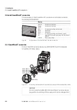
4.2.2.4 Network – S4: Operation, profile 2
If the profile 2 with
PNU 928.0 = 1 - 5
is used then the general state diagram
shown below will apply. The transitions will take place when the correspond-
ing bits’ state is changed.
Figure 16:
State diagram: Network – S4 (profile 2)
S4.3: Paused Operation
Bit 8 = 1; Bit 10 = 0
S4.4: Ramping Down Operation
Bit 8 = 1; Bit 10 = 0
S4.2: Ramping Up Operation
Bit 8 = 1; Bit 10 = 0
S4.5: TOR Operation
Bit 8, 10 = 1
S4.1: Idle Operation
Bit 8, 10 = 0
Bottom
of Ramp
Top of Ramp
Ramp Up
Bit 4 = 1 (EN_Ramp) and
Bit 5 = 1 (Freeze) and
Bit 6 = 0 (EN_Set)
Ramp Down
Bit 4 = 1 (EN_Ramp) and
Bit 5 = 1 (Freeze) and
Bit 6 = 1 (EN_Set)
Ramp Up
Bit 4 = 0
(EN_Ramp)
Bit 4 = 1 (EN_Ramp) and
Bit 5 = 1 (Freeze) and
Bit 6 = 1 (EN_Set)
Ramp Down
Bit 4 = 1 (EN_Ramp) and
Bit 5 = 1 (Freeze) and
Bit 6 = 0 (EN_Set)
Pause
Bit 4 = 1 (EN_Ramp) and
Bit 5 = 0 (Freeze) and
Idle
Bit 4 = 0
(EN_Ramp)
Idle
Содержание PowerXL DX-NET-SWD
Страница 4: ...II ...
Страница 10: ...0 About this Manual 0 6 Units 6 DX NET SWD 06 13 MN04012009Z EN www eaton com ...
Страница 16: ...1 Device series 1 7 Disposal 12 DX NET SWD 06 13 MN04012009Z EN www eaton com ...
Страница 26: ...3 Installation 3 4 Dismantling 22 DX NET SWD 06 13 MN04012009Z EN www eaton com ...
Страница 64: ...4 Commissioning 4 5 SmartWire DT diagnostics 60 DX NET SWD 06 13 MN04012009Z EN www eaton com ...
Страница 68: ...5 Appendix 5 2 SmartWire DT 64 DX NET SWD 06 13 MN04012009Z EN www eaton com ...


