Modbus MS Card
– User Manual
34009048XT_EN/AD
Page
7/55
3 Installation
3.1 RS232 link configuration and connection
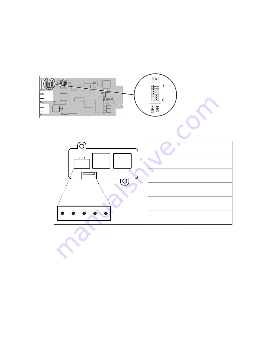
Set the SA2 switches like below:
The next figure shows the details of the connection in RS232 mode:
JBUS/232/485
OV T+ T- R+ R-
UPS Data
Settings/Sensor
ETHERNET
100M
ACT
RS232
Tx
Rx
1
2
5
4
3
XXXXXXXXXXXX 66103
Pin number
Function
1
Received data (input)
2
Not connected
3
Transmitted data
(output)
4
Not connected
5
Signal Ground


