


i-on40
Page 3
2. Before You Begin
Preparation
Before installation you should carry out a survey
of the site. You need to know how many and what
kind of detectors will be transmitting to the control
unit. You also need to assess where the control
unit must be placed in order to receive radio
signals from the detectors successfully.
Radio Site Survey
You should conduct signal strength tests before
installation.
Eaton’s Security Business produce
the Scantronic 790r hand held signal strength
meter and 734r-01 test transmitter for this
purpose. Please read the 790r manual for details.
Please be aware of the following:
The 790r signal strength meter readings
should be used only as an guide when initially
checking the site.
A reading of four green LEDs or higher
indicates an acceptable signal strength.
Once you have installed the alarm system you
should put the control unit in the Installer test
menu and test the received signal strength
from each radio transmitter.
A signal strength reading of two or more units
by the control unit from each transmitter
should provide reliable operation in the
installed system. (
Note:
if you take the signal
strength using i-on Downloader or the web
browser interface while the panel is in user
mode then the minimum acceptable signal
strength is four units. Ensure that the control
unit is in Installer mode when reading signal
strengths remotely.)
When you record the signal strength readings
for later inspection, you should record the
readings taken from the control unit of the
installed system while it is in the Installer
Menu.
Please be aware that the signal strength received
from a transmitter can change after installation
because of local environmental changes. For
example, users switching on laptops nearby, or
moving metal cabinets from their original position
can all affect the signal from a transmitter. Please
read
Eaton’s Security Business publication
”Guidance Notes for Wireless Alarm System
Installations” obtainable from
www.coopersecurity.co.uk for more information
about the factors affection radio signal strength.
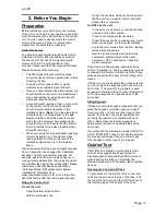
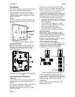
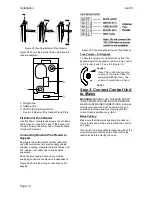
Siting the Control Unit
Do site the unit:
Upright (battery at the bottom).
Within a protected zone.
As high as possible. However, do make sure
that the unit is on a similar level to the other
transmitters or receivers.
Do NOT site the unit:
In the entry or exit zones, or outside the area
covered by the alarm system.
Close to or on large metal structures.
Closer than one metre to mains wiring, metal
water or gas pipes, or other metal surfaces.
Lower than two metres from the floor (ideally).
Inside metal enclosures.
Next to electronic equipment, particularly
computers, photocopiers or other radio
equipment, CAT 5 data lines or industrial
mains equipment.
Note: Some window glasses, especially those
sold as “insulating” or “energy conserving” may be
coated with thin metal or conducting films. These
glasses are particularly poor at transmitting radio
waves.
If fitting two or more keypads then make sure that
you do not place the keypads within one metre to
each other. (The proximity tag readers in each
keypad will interfere with each other.) Remember
not to place keypads on opposite sides of the
same wall.
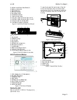
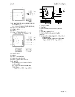
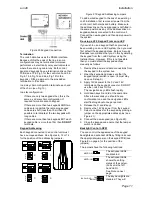
Siting Keypads
If fitting two or more keypads make sure that you
place the keypads more than one metre apart
from each other, or from any other type of prox
reader. (At less than one meter separation the
proximity tag readers will interfere with each
other.) Remember not to place keypads or
external prox readers on opposite sides of the
same wall.
If you intend to fit external prox reader KEY-EP to
a KEY-KPZ01/KP01, then do not site the external
prox reader itself closer than one meter to any
other keypad or other type of prox reader.
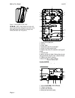
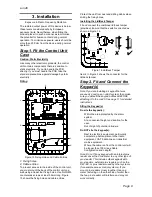
Guided Tour
CAUTION: The printed circuit boards for the i-
on40 and its keypads have been tested for
Electromagnetic Compatibility (EMC). However,
when handling the pcbs you must take the
standard precautions for handling static sensitive
devices.
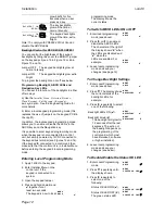
Opening the Control Unit Case
To gain access to the interior of the control unit
undo the two screws at the top of the case. Pull
the top of the lid down, and then lift the lid out of
the retaining lugs at the bottom of the case.
Содержание i-on40
Страница 1: ...i on40 Security System Installation Guide Issue 7...
Страница 4: ...i on40 Page iv This page is intentionally blank...
Страница 34: ...i on40 Page 30 NOTES...
Страница 35: ...i on40 Page 31 NOTES...


