i-on40
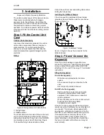
Installation
Page 11
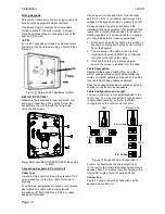
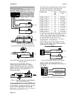
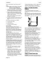
Figure 20 Keypad Connection
Termination
The i-on40 data bus uses the RS485 interface.
Because of this the ends of the line in some
configurations may be terminated to improve
performance in electrically noisy environments or
where there are long cable runs. Both control
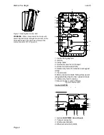
panel and keypads have a termination link on their
PCBs (see 10 in Fig 3 for the control unit and 5 in
Fig 8, 1b in Fig 12 and 6b in Fig 14 for the
keypads). Fitting a jumper to the pins adds a
termination to the cable.
In a daisy chain configuration terminate each end
of the chain (see Fig 19 ).
In a star configuration:
If there are only two keypads then this is the
same as a daisy chain configuration. If
required terminate at each keypad.
If there are more than two keypads AND two
cables are long while the remaining keypad
cables are short (less than 10m) then it is
possible to terminate at the two keypads with
long cables.
If there are more than two keypads BUT each
keypad cable is more than 10m then
DO NOT
terminate.
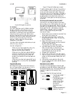
Keypad Addressing
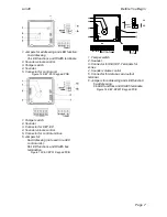
Each keypad connected to an control unit must
have a unique address. See Figures 8, 12 or 14
for the position of the addressing jumpers.
Figure 21 Keypad Addressing Jumpers
To add a wired keypad to the bus of an existing i-
on40 installation, first remove all power from the
control unit, both mains and battery. Make sure
the address link on the new keypad is not fitted in
the same position as any of the address links on
keypads already connected to the control unit.
Connect the new keypad and then apply power to
the system.
Re-using a V2.0 Keypad From an i-onEX
If you wish to use a keypad that has previously
been working on an i-onEX system, then you must
first default the keypad address.
Eaton’s Security
Business recommends that you do this by deleting
the keypad from the i-onEX system using the
Installer Menu. However, if this is not possible
then you must default the keypad address
manually as follows:
1. Remove the power and data connections from
the keypad to the system bus.
2 Open the keypad and make sure that the
keypad tamper switch is open. (It must stay
open until step 9.)
3. Apply 12Vdc power to the 0V and 12V
terminals on the keypad connector. DO NOT
use the i-on40 bus for this.
The navigation key LEDs flash rapidly.
4. Hold down keys D and
at the same time.
After a few seconds you should hear a
confirmation tone and the navigation LEDs
start flashing about once per second.
5. Release the D and
keys.
6. Remove the 12V dc power from the keypad.
7. Select an address for the keypad by placing a
jumper on the appropriate address pins (see
Figure 21).
8. Connect the new keypad (see Figure 20).
9. Close the keypad and ensure that the tamper
switch is closed.
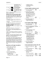
Backlight Control I-KP01
You can control the appearance of the keypad
backlights and set/unset LEDs by fitting links over
the appropriate jumpers on the keypad PCB (see
Figure 8 on page 6 for the position of the
jumpers).
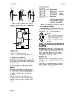
The jumpers have the following functions:
The set/unset LEDs
are disabled.
The set/unset LEDs
shows the setting
status of the system.
(Full set is the left
hand LED.)
See Note on next
page.
The key backlights are
disabled. They will
4
3
2
4
3
2
1
2
4
3
4
3
2
4
3
2
ON
BRIGHT
BL
ABCD-ON
ON
BRIGHT
BL
ON
BRIGHT
BL
ABCD-ON
ON
BRIGHT
BL
ABCD-ON
ON
BRIGHT
BL
ON
BRIGHT
BL
ABCD-ON
ON
BRIGHT
BACKLIGHT
BACKLIGHT
BACKLIGHT
ABCD-ON
ON
BRIGHT
ON
BRIGHT
ABCD-ON
Содержание i-on40
Страница 1: ...i on40 Security System Installation Guide Issue 7...
Страница 4: ...i on40 Page iv This page is intentionally blank...
Страница 34: ...i on40 Page 30 NOTES...
Страница 35: ...i on40 Page 31 NOTES...


