Eaton i-on40 Скачать руководство пользователя страница 25

i-on40 

Page 21 

4. Programming 

This section is summary of the Installer Menu on 
the i-on40. Please see the 

i-on Range 

Engineering Guide 

for a more detailed description. 

Entering the Installer Menu 

1.  Make sure the system is unset and showing 

the standby screen (time and date). 

2.  Key in the Installer access code. When 

delivered from the factory the default Installer 
access code is “7890”. The default user code 
is “1234”. 
As you start to key in the code the display 
shows: 





When you key in the last digit of the Installer 
access code the display shows:  





Notes: 
1. You will see this screen the first time you enter 
the Installer menu on a new control unit, or if you 
have restored Factory Defaults. You can disable 
this feature by using the Installer menu option 

System Options - User Access – User Code Required

2. If you set 

User Code Required

 to NO then the 

control unit no longer complies with EN50131. 
This option complies with BS8243 only if the user 
has given written consent. 
3. If you key in an access code incorrectly, the 
display shows four “stars”. Key in the code again. 
If you key in a total of four incorrect codes then 
the system locks you out for 90 seconds. 

3.  Key in the default user code (see Note 

below). 

The display shows: 





4.  Press 

 or 

 to display more items from the 

menu. 

Each item appears on the bottom line of the 
display in turn, for example: 





5.  Press 

 to select that item of the menu. 

The option you selected now appears on the 
top line. If there are any sub-options for that 
selection, then the first of them appears on 
the bottom line, for example: 





You can press 

 or 

 to display the other 

sub-options. 

Leaving the Installer Menu 

If you wish to leave the Installer Menu at any time. 

1.  Press 

 until the display shows the words 

“Leave installer mode?”. 

 

  

2.  Press 

 to leave Installer menu. 

(Press 

 if you do not want to leave the 

menu.) 

The display shows the time and date. 





The system is ready for use. 

Note:  If you attempt to leave the Installer Menu 
when a detector tamper is active then the keypad 
displays a fault message telling you which 

detector is causing the problem. Press 

 to 

return to the Installer Menu. You must either close 
the detector tamper or delete it from the system 
before you can leave the Installer Menu. 

Important! 
Saving Changes 

When you make changes to the Installer Menu the 
control unit holds those changes in temporary 
memory until you leave the Installer Menu. As you 
leave the Installer Menu the control unit writes 
those changes into a permanent store. If you 
remove all power BEFORE you leave the Installer 
Menu then the control unit will lose your changes. 
Note that this does not apply if you restore 
Factory Defaults, that change takes place 
immediately. 

Restoring Access Codes 

If the user and/or Installer codes are lost then you 
must restore all user information to its factory 
defaults. All prox tags, remotes and radio HUDs 
will be deleted. 

1.  If possible, enter the Installer menu. 

Note: If you cannot enter Installer Menu then the 
control unit will start a tamper alarm when you 
open the control unit lid. 

2.  Remove mains power, then open the case 

and disconnect the battery. 

Note: This procedure will not work if the control 
unit lid tamper remains closed. 

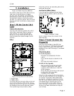
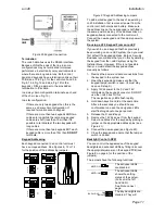
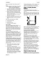
3.  Identify the Reset Codes pins on the main 

PCB (see Figure 3). 

4.  Short the Reset Codes pins together using a 

screwdriver or jumper link. (Keep the short on 
until step 6.) 

5.  Apply mains power. 

Содержание i-on40

Страница 1: ...i on40 Security System Installation Guide Issue 7...

Страница 2: ...but will not damage the equipment Caution Describes actions that will physically damage the equipment and prevent its proper function WARNING Describes actions that are hazardous to health or cause in...

Страница 3: ...on 15 Step 4 Connect Wired Zones 15 Four Wire Closed Circuit Connections 15 Two Wire Closed Circuit Connections 15 Fully Supervised Loop Connections 15 Connecting Wired Zones on KEY KPZ01 only 16 Step...

Страница 4: ...i on40 Page iv This page is intentionally blank...

Страница 5: ...odules are i dig02 ATS2 A switched telephone network PSTN module that allows the control unit to report alarm information using standard protocols such as Fast Format SIA and Contact ID and can also s...

Страница 6: ...lease see the i on Web Server Setup Guide for more instructions Note that Eaton s Security Business recommends using Internet Explorer Other browsers may not be fully compatible with the web browser i...

Страница 7: ...persecurity co uk for more information about the factors affection radio signal strength Siting the Control Unit Do site the unit Upright battery at the bottom Within a protected zone As high as possi...

Страница 8: ...Connector pins for Lid Tamper 5 Printed circuit board PCB 6 Cable entry holes for detector and keypad wiring 7 Transformer 8 Mains connector block Note yellow power rating label fitted next to the con...

Страница 9: ...y not used in UK Figure 4 Control Unit Main Connectors i KP01 Controls and Displays 1 LCD display 2 x 20 characters 2 Programming keys 3 Navigation keys 4 Alert LEDs 5 Setting and unsetting keys 6 Pan...

Страница 10: ...losed and open 6 Hold Up Alarm HUA keys 7 Number text keys Figure 9 KEY K01 KP01 KPZ01 Controls and Displays Opening the KEY K01 KP01 KPZ01 To open the unit unclip the caps covering the screws on the...

Страница 11: ...onnector for control unit bus 6 Jumpers for 6a Addressing not used in i onEX control units 6b LED functions and RS485 bus termination Figure 13 KEY KP01 Keypad PCB 1 Tamper switch 2 Sounder 3 Connecto...

Страница 12: ...an i on40 control unit two i kp01 keypads and 15 wired PIRs the system takes the following total quiescent current Device Current Control unit PCB 130mA 15 x PIRs at 15mA each 225mA i sd02 communicato...

Страница 13: ...ck Tamper Fit and connect the combined lid back tamper provided Ensure that the switch is oriented as shown in Figure 16 Figure 16 Lid Back Tamper Item 2 in Figure 3 shows the connector for the lid ba...

Страница 14: ...if the installation site has equipment that produces high levels of R F Radio Frequencies for example welding equipment If screened cable is required you should keep to the following guidelines 1 Avoi...

Страница 15: ...m Re using a V2 0 Keypad From an i onEX If you wish to use a keypad that has previously been working on an i onEX system then you must first default the keypad address Eaton s Security Business recomm...

Страница 16: ...ypad s local programming mode Entering Local Programming Mode 1 Apply 12Vdc to the keypad 2 Enter Installer Menu on the control unit if the keypad is connected to a system 3 Open the keypad tamper 4 P...

Страница 17: ...r KEY EP used by the KEY KPZ01 1 LED window 2 Retaining Screw 3 Removable Fixing Plate 4 Permanently attached cable Figure 22 External Prox Reader KEY EP Siting the External Prox Reader Do site the Ex...

Страница 18: ...igure 25 shows the wiring connections at the keypad Figure 25 Connecting the External Prox Reader Tone Volume All Keypads To alter the volume of non alarm tones from the keypad adjust the keypad sound...

Страница 19: ...tem Options Wire Zone Type Panel Zones option and select 2 wire CC If required you can use one pair of zone terminals as a common tamper provided you program that zone with the type Tamper from the In...

Страница 20: ...d 3 Zone 1 35 35 Alarm Keypad 3 Zone 2 36 35 Tamper Keypad 4 Zone 1 33 33 Alarm Keypad 4 Zone 2 34 33 Tamper To select the wiring type for the keypad zones use Installer Menu System Options Wired Zone...

Страница 21: ...an example of a general method of using the outputs to connect a wired sounder It is possible to program the TR terminal on the control unit see item 8 in Figure 4 as either CC or FSL Use Installer Me...

Страница 22: ...ector The communicator must provide 12Vdc to indicate a line fault for example if the Line Fault output at the communicator uses a relay connect the common terminal of the relay to 12Vdc and the norma...

Страница 23: ...oad the Profile Or Press to start with a blank system Note The Profile may not be EN50131 compliant The factory default is EN50131 compliant The control unit loads your choice of profile and then show...

Страница 24: ...of the Installer Menu 5 Assemble and close the control unit a Hook the lid of the control unit into the bottom of the case b Close the lid and then tighten the two fixing screws NOTE It is possible fo...

Страница 25: ...other sub options Leaving the Installer Menu If you wish to leave the Installer Menu at any time 1 Press until the display shows the words Leave installer mode 2 Press to leave Installer menu Press if...

Страница 26: ...Installer Menu and then leave it again The navigation key LEDs should now glow green Note The log is protected and cannot be erased by the Installer Restoring Factory Defaults If you wish to restore a...

Страница 27: ...Way Set Instant Duress Enable User reset Zone alarms 7 Zone tampers System tampers Confirmation UK Confirmation Mode Basic DD243 BS8243 Confirmation time 8 After entry 8 Entry keypad lock 8 Sounder o...

Страница 28: ...Appears only if System Options Confirmation Mode is BS8243 10 Appears only when Masking is ON 11 Appears only in EUR version 12 Appears in this position only in part setting systems 13 Appears only wh...

Страница 29: ...ntly clean the lenses of any PIRs with a clean soft dry cloth Do not use water solvents or any proprietary cleaning materials Walk test all detectors Test any external sounders and strobes Replacing o...

Страница 30: ...ocking Blocked for 90s after four incorrect codes or prox tags in series Blocked for a further 90s after each additional incorrect code or prox tag until next correct code or prox tag entered Proximit...

Страница 31: ...to EN50130 4 Emissions Conforms to EN61000 6 3 Outputs O P 1 2 Voltage free single pole relay contacts rated 24VDC 1A O P 3 4 Open collector transistor 12VDC when inactive 0V when active 500mA max Plu...

Страница 32: ...el top button is disabled 706rEUR 00 Two button HUD tilt switch transmitter 710rEUR 00 Two button HUD 726rEUR 50 Long range hand held HUD 726rEUR 60 Short range hand held HUD Detectors 713rEUR 00 Pet...

Страница 33: ...N Communication ARC only i gsm02 GSM communications module i sd02 PSTN Communication module with speech dialling Accessories 703rEUR 00 4 channel 2 zone transmitter 762rEUR 00 Two Channel Receiver 768...

Страница 34: ...i on40 Page 30 NOTES...

Страница 35: ...i on40 Page 31 NOTES...

Страница 36: ...ww coopersecurity co uk Product Support UK Tel 44 0 1594 541978 Available between 08 30 to 17 00 Monday to Friday Product Support Fax 01594 545401 email techsupport coopersecurity co uk Part Number 12...

Отзывы: