


8
XCHARGEIN DC 22 INSTALLATION MANUAL
MN192004EN September 2021 www.eaton.com
00 Title
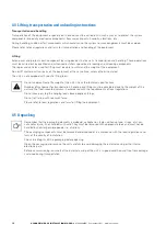
3.3 Top and bottom views
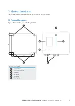
Figure 2. Left and right views of xChargeIn DC 22
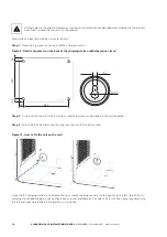
3.2 Left and right views
Figure 3. Top and bottom views of xChargeIn DC 22
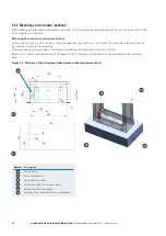
Number Description
1
Power input cable gland
2
Ethernet cable gland
3
CHAdeMO cable gland
4
CCS cable gland
5
Optional cable entries (knockout holes)
6
Screws to open/close the front door
7
Emergency stop button
1
5
3
4
6
2
7
Number Description
1
Air flow grid
1


