


- Page 2 -
I.B. 8926-1
THE MOTOR CONTROL CENTER
Although the Cutler Hammer Freedom 2100 Motor Con-
trol Center may be joined to existing Five Star, Series
2100, and Advantage installations using the same splice
bar kits common to both. Units designed for the Free-
dom 21 00 can be mounted in Five Star Series and Se-
ries 21 00 sections, but the opposite is not recommended,
because Five Star and Series 21 00 units may lack ter-
minal blocks and sufficient interrupting capacity. The
Freedom 2100 MCC may be joined to existing Cutler-
Hammer Freedom Unitrol and Fl 0 Unitrol MCC’s with a
special splice bar kit, but units are not interchangable.
CONTROL CENTER NOMENCLATURE
The numbers shown in parentheses in the following text
refer to the balloon legends in Figure 2.
The Cutler Hammer Freedom 21 00 Motor Control Center
consists of one or more totally enclosed, dead front, free
standing structural assemblies (1 7) 90 inches high which
are compartmentalized to house individual control units.
(2) With control units mounted in the front side only, the
structure may be 16 or 2l inches deep. For mounting
units back-to-back, the structure is 21 inches deep. Steel
covers (7) enclose the structure at the top, sides and at
the rear of front-mounted-only structures.
Each control center contains a main horizontal bus sys-
tem (9) mounted at the top and extending across the
length of the control center.
A vertical bus system (8) installed in each vertical sec-
tion is connected to the horizontal bus to feed the indi-
vidual control units. (6) The vertical bus is isolated by a
full height barrier. (14) An optional labyrinth barrier pro-
vides both isolation and insulation. An automatic shut-
ter is included with the labyrinth barrier system to cover
the stab openings for each control unit.
At the top of each section, a door provides ready access
to the top horizontal wireway (11) and ground bus (10).
The horizontal wireway is isolated from the bus systems
by steel barriers (12) which can be removed for installa-
tion and maintenance operations. Adequate space is
provided for control wiring and top cable entry.
At the bottom of each section, a door (18) provides ready
access to the bottom horizontal wireway, (19) and neu-
tral bus (if provided). The bottom of each section is com-
pletely open to provide unrestricted bottom entry of ca-
ble and conduit. Channel sills may be installed across
the bottom of the control center if specified, and an op-
tional bottom plate may also be specified.
A vertical wireway 8 inches deep, (16) extending the full
90 inch height of the control center is located to the right
of each unit compartment. This wireway is covered by
two hinged doors (15) and contains cable supports to
secure wire bundles and cables. The vertical wireway
joins the horizontal wireway at top and bottom to pro-
vide unobstructed space for interwiring.
Each vertical section provides space to mount up to six
controller units (2) with a minimum height of 12 inches,
in increments of six inches, for a total of 72 inches of
usable space. Controllers through NEMA Size 5 are
drawout type (except reduced-voltage starters). These
drawout unit assemblies are a completely self-contained
package consisting of a steel enclosure, operating han-
dle and electrical components. The drawout assembly
slides into its compartment on guide rails (1 3) to pro-
vide easy withdrawal and reinsertion andto ensure pre-
cise alignment of the unit stabs with the vertical bus.
Each drawout unit is held in place by a single quarter-
turn latch (3) which can only be engaged when the unit
stabs are fully mated with the vertical bus. Each unit
has a separate door, (1) held closed by a minimum of
two quarter-turn fasteners.
The operating handle on the controller unit (4) moves
vertically. In the ON or TRIPPED positions, the handle
interlocks with the unit door to prevent its opening. In
this position, authorized personnel can open the door by
turning the defeater mechanism screw. (21)With the unit
door open and the operating handle in the ON position,
another interlock to the divider pan prevents removal of
the unit. This same interlock prevents insertion of the
unit unless the handle mechanism is in the OFF posi-
tion. To ensure that units are not energized accidentally
or by unauthorized personnel, the handle mechanism
can be padlocked in the OFF position.
Part 1
GENERAL INFORMATION
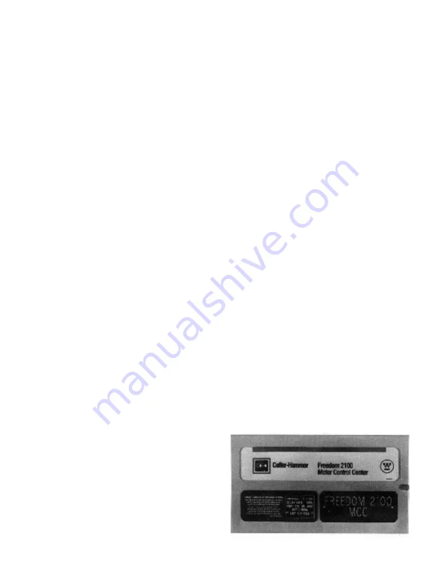
Fig. 1 Nameplate
Содержание Freedom 2100
Страница 26: ...Page 26 I B 8926 1...
Страница 32: ...Page 32 I B 8926 1 Part 11 PLAN VIEWS...
Страница 33: ...Page 33 I B 8926 1...


