


1
FC18 Fan controller user manual
FC18 FAN CONTROLLER
www.eaton.com
1. Introduction
•
The FC18 Fan Controller can be connected to a Cooper
analogue addressable fire alarm control panel by means
of the comms Loop utilizing only one address.
•
There are 6 channels per Fan Controller capable of
controlling & indicating 6 individual Fans.
•
All FC18 Fan Controllers are programmed individually
by means of the unique easy to use Cooper Site
Installer PC software.
•
Each channel is programmed to an output device and
feedback input device that can reside on any loop on
any panel on the network to control & monitor the
status of the Fan.
•
The CFC301 which takes 2 addresses on the loop,
one for the control output which appears as a ZMU
and one for the feedback input which appears as a
technical input.
•
The MCIM can also be used as the feedback input.
•
The MCOM can also be used as the control output
but is limited to 20 per loop.
•
The MCOM-S can also be used as the control output
and is limited to 60 per loop but as it auto-learns
and behaves like a sounder it will activate during an
evacuation.
•
The MCOM-FC can also be used as the control
output and is limited to 60 per loop but even though it
auto-learns as a sounder it will not react to evacuations.
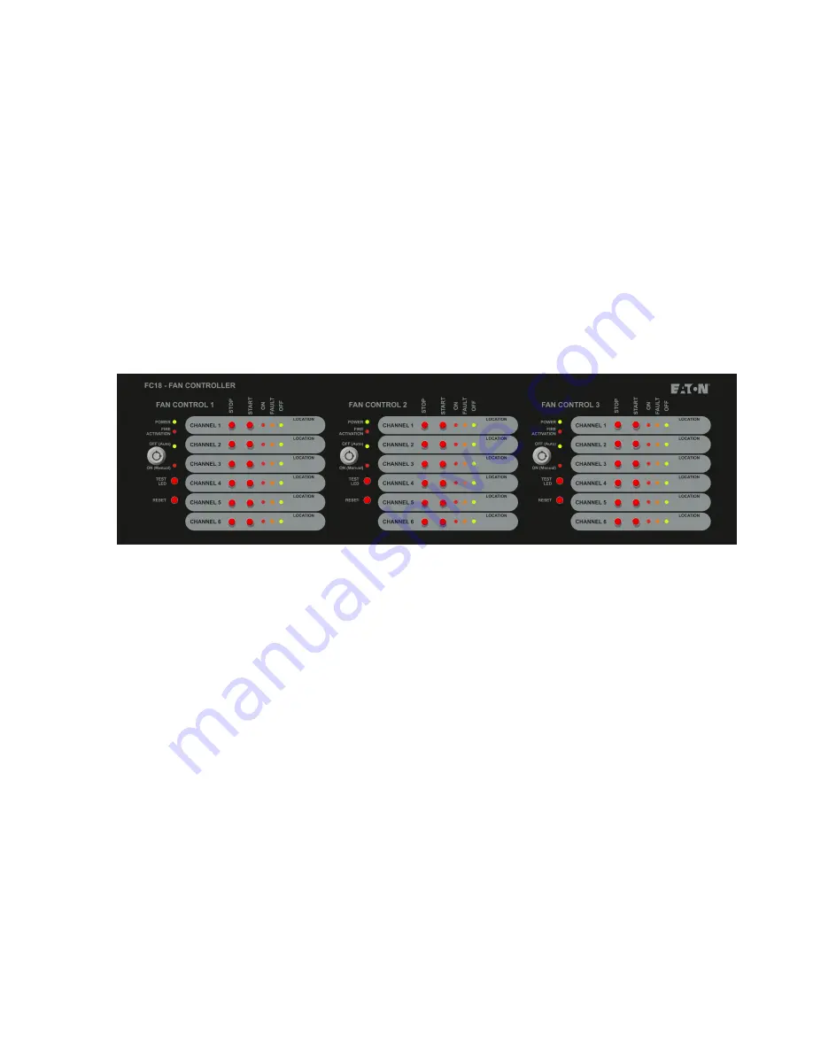
Status LED
•
Power LED (Green) when Fan Control is working
normally, the LED on
•
Fire Activation LED (Red) Operates when fire alarm is
received from main panel
Controls:
Key switch
•
Auto/Manual key switch: used to select auto or
manual control
•
Select Auto Mode: Green LED. The Fan Control
operation is initiated by the state of the Fire Panel
•
Select Manual Mode: Red LED, The Fan Control
operation is controlled by the “Stop/Start” buttons
on the individual channels
Reset button
•
Press the button to reset Fan Control. Reset from the
main panel will not reset the fan controller
Test LED
•
Pressing the test LED button will start the control panel
self-test
Channel 1-6:
Start/stop buttons
•
Start button: press the button, start one device.
(Requires to start two channels of the one device)
•
Stop button: press the button to stop one device.
(Requires to stop two channels of the one device)
LED indication
•
ON LED (Red) Activated when the device receives
feedback and the Start button has been pressed,
otherwise, off.
•
Fault LED (Amber) Activated when No Feedback has
been received after Start has been pressed or Stop
button has been pressed but feedback has been
received and/or Open Circuit/Short circuit has been
reported, otherwise off.
•
OFF LED (Green) Activated when the stop button has
been pressed and No Feedback has been received or
no feedback is being received, otherwise off.
2. Overview
PR209-166-505-08
January 2018
Содержание FC18
Страница 1: ...FC18 Fan controller user manual...


