


18
5. System Self-supervision
EAFR-101S Arc Point Sensor Relay User Manual
MN026005EN February 2016 www.eaton.com
4.1.2 EAFR-01 Point Sensor Technical Data
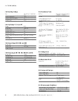
Table 9. EAFR-01 Point Sensors Technical Data.
Light Intensity Threshold
8,000 Lux/25,000 Lux/50,000 Lux
Detection Radius
180 Degrees
Mechanical Protection
IP 64
Sensor Wiring Arrangement
Two Wires and Shield
Sensor Cable Specification
Shielded Twisted Pair 0.75 mm2
(0.03 in.2)
Maximum Sensor Cable Length per
Sensor Channel
200 m (656 ft)
Operating Temperature
-20 to 85°C (-4 to 185°F)
5. System Self-supervision
The EAFR-101S includes an extensive self-supervision fea-
ture. Self-supervision includes both internal functions and
external connections. The self-supervision module monitors
power supply, hardware and software malfunctions, and
binary input connection and sensor problems. Dipswitch
settings are also supervised by comparing the actual value
with stored non-volatile memory data (see Section 3.3.1:
Auto Configuration [System Setup]).
In a healthy condition, the POWER LED is on and the
System Failure (SF) relay is energized. If the self-supervi-
sion function detects a faulty condition or the power supply
fails, the self-supervision relay is released and the ERROR
LED is illuminated.
If a sensor failure occurs, the relay will go into ERROR
mode. The ERROR LED will illuminate, the SF relay will
released-energize, and the corresponding faulty sensor
channel LED will start blinking. In this situation, the relay
is still in the protection mode, but with the faulty sensor
channel blocked. If the error is resolved, the ERROR LED
will automatically clear the SF-status and failed sensor chan-
nel LED will remain in blinking status. This means that the
SF relay will energize and the ERROR LED will turn off. If
one or more of the sensors are disconnected, the healthy
sensors remain in use and relay remains operational. The
EAFR-101S will remain in error mode until the disconnected
sensors are repaired.
If a dipswitch setting is changed after the auto-configuration
function (see Section 3.3.1: Auto Configuration) has been
executed, the relay will go into SF alarm mode. The con-
figured (stored) setting is however still valid and the relay is
still operational.
6. Application Examples
The EAFR-101S may be applied to a variety of power switch-
gear and control gear layouts and technologies. Some typi-
cal applications are described in this section. Please consult
your nearest Eaton representative for a solution to your
particular application.
6.1 MV or LV Double Busbar Application with Current
and Light condition
The EAFR-101S may be applied requiring both over-current
and arc light conditions for trip. In this application, tripping
is performed only if both conditions are fulfilled simultane-
ously. Typically, the over-current condition is obtained from
an EAFR-110 relay or monitored by non-Eaton products (e.g.
generic feeder protection relay) and the total operation time
is then dependent on device feeding the over-current signal
to EAFR-101S.
Figure 17 shows an example of a double busbar arc pro-
tection system applying both over-current and arc light for
tripping. S1 channel is typically monitoring the outgoing
cable compartment. S2 channel is monitoring the breaker
compartment. S3 and S4 are respectively monitoring the
reserve busbar and main busbar. The busbar arc light fault
information is sent out through the binary output channel
BO1 (main busbar) and channel BO2 (reserve busbar).
Figure 16. Double Busbar Application.
T3(Trip Alarm )
T1
S1
S2
EAFR-101S
BO2
BI 3
BI
1
BI2
S3 S4
BO1
re
se
rv
e
M
ain
EAFR-101S
BI1
BI2
SET
BI4
BI5
BI6
BO1
BO2
BO3
S2
S1
S3
ERROR
POWER
T2,T3
BI3
T1,T3
S4
Eaton Arc Flash Relay
CB


