


16
3. Operation and Configuration
EAFR-101S Arc Point Sensor Relay User Manual
MN026005EN February 2016 www.eaton.com
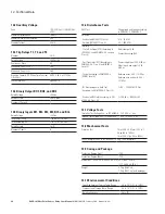
Figure 13. EAFR-101S Configuration Selection 10.
3.5.1.10 Configuration Selection 10
The EAFR-101S logic Configuration 10 is very similar to
Configuration 9. S2 is used for monitoring the incoming
feeder breaker compartment. S3 monitors the reserve bus-
bar. S4 monitors the main busbar compartment. The con-
tact T1 is responsible for tripping the section circuit breaker.
T2 is responsible for tripping the tie circuit breaker. BI1
and BI2 are responsible for recognizing the incoming circuit
breaker position. BI3 receives over-current information from
the EAFR-110P of the incoming feeder. BI4, BI5, and BI6 are
used for sending light information from a different location
of the busbar. BO1, BO2, and BO3 send arc fault informa-
tion to the incoming feeder units and intermediate units.
The CBFP feature is applied into this configuration.
S1
S2
S3
S4
BI1
BI2
BI3
BI4
BI5
BI6
T1
T2
T3
BO1
BO2
BO3
&
OR
&
SW1/8
&
OR
&
SW1/8
&
OR
&
SW1/8
&
OR
&
SW1/8
OR
OR
OR
OR
&
OR
OR
&
&
OR
OR
OR
&
&
SW1/7
&
OR
SW1/5
!SW1/5
&
SW1/5
!SW1/5
SW1/5
!SW1/5
OR
SW1
Light
S1: Light
Latch
100 ms
150 ms
Non Latch
Light and Current
Light and Current
Configuration Select:
8
7
6
5
4
3
2
1
3.6 Non-volatile Memory
All critical system data, including dipswitch settings and
auto-configuration file described in Section 3.3.1, are stored
in EPROM non-volatile memory to ensure correct operation
and full self-supervision, even if auxiliary power is temporar-
ily lost.
Also, all LED indications described in Section 3.1 are stored
in non-volatile memory in order to provide quick recovery of
the system status indication, even if auxiliary power is tem-
porarily lost. This feature is especially important if auxiliary
power is lost after tripping.
Non-volatile memory does not require a power supply to
maintain information and will retain settings and indications
permanently without power.


