17
4. Arc Sensors
EAFR-101S Arc Point Sensor Relay User Manual
MN026005EN February 2016 www.eaton.com
4. Arc Sensors
The EAFR series provides the choice of different types
of arc sensors to be utilized in different units and differ-
ent switchgear types, according to the specific application
requirements. Available sensor types are arc light point sen-
sors and arc light fiber optic loop sensors.
Arc light point sensors are typically installed in metal clad
compartments, providing quick accurate location of the fault-
ed area. Arc light fiber loop sensors are installed typically to
cover a wider protected area with one fiber when no need
for more exact fault location exists.
4.1 Arc Light Point Sensor EAFR-01
The EAFR-01 is an arc light point sensor with a light sensi-
tive photodiode element activated by receiving arc light.
The EAFR-01 arc sensors should be mounted in the switch-
gear cubicles in such a way that the light sensitive part can
receive light from the protected area. Typically, one sen-
sor per closed metal clad compartment is used. In open
spaces, such as the busbar section, arc sensors should be
mounted at a maximum of two meters (6.56 ft) apart.
The fixed light sensitivity of the EAFR-01-A sensor is 8,000
Lux. The sensor does not require any user settings. The
point sensor’s light detection radius is 180 degrees. Other
point sensors are available with different Lux sensitivities,
EAFR-01-B at 25,000 Lux and EAFR-01-C at 50,000 Lux.
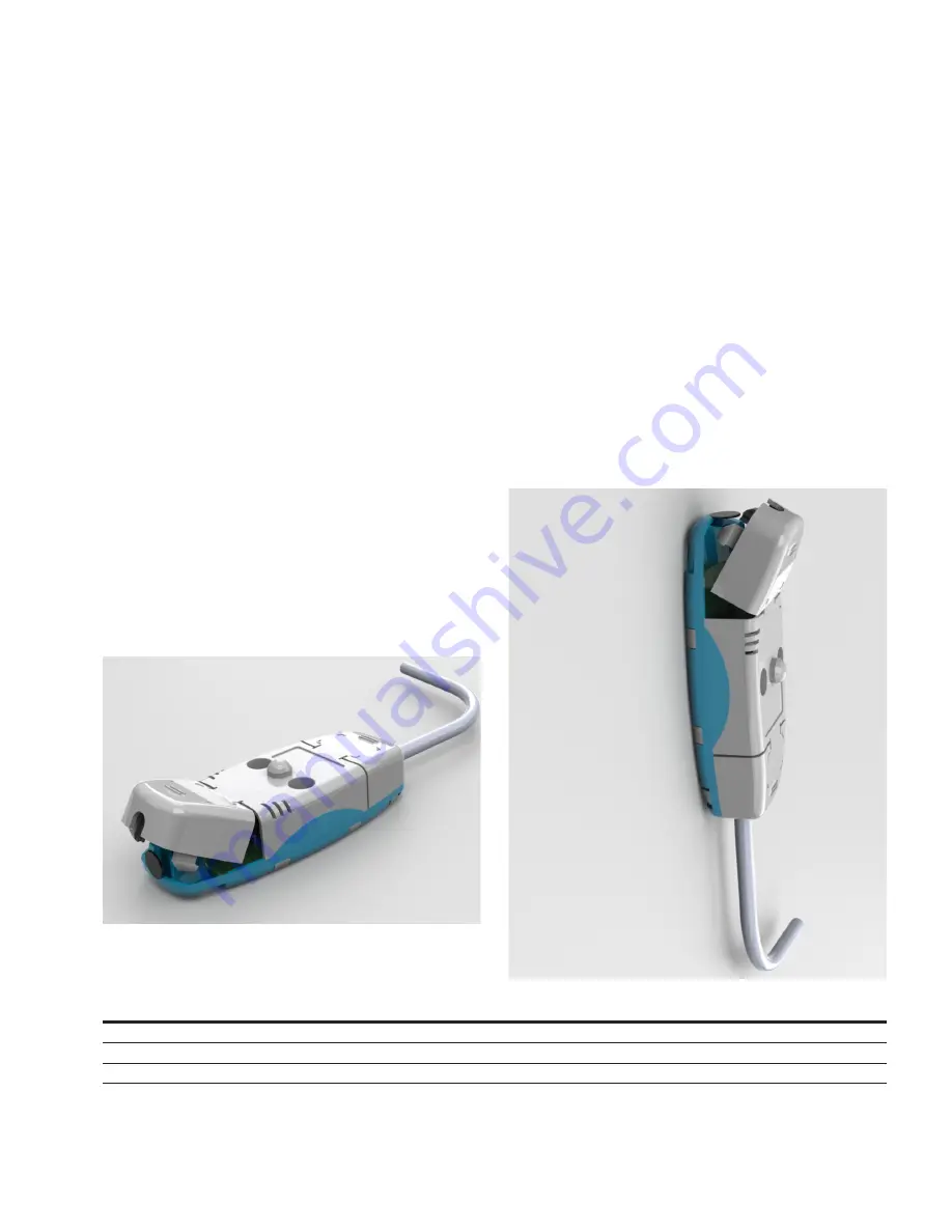
Figure 14. EAFR-01 Arc Light Point Sensor.
4.1.1 EAFR-01 Installation and Wiring
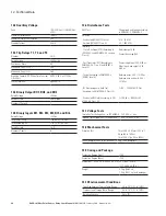
The EAFR-01 point sensor can be installed either on or
through the compartment wall. An example of on the
wall mounting is seen in Figure 16. The EAFR-01 is fixed
against the wall using two screws. The same screw pat-
tern is utilized in a through wall mounting arrangement. In
this arrangement the unit is turned around and the point
of the eye of the photodiode sensor protrudes through a
small hole cut in the wall. The point of the sensor now
faces the compartment to be protected. This allows for the
body of the sensor and cabling to be located outside the
compartment. For both types of installation, two screws
are attached from the back side of the sensor. No external
mounting plates are needed.
The EAFR-01 comes without the connection cable.
Connection cable installation on site is simple. The cable
connectors are located beneath the covers that can be
conveniently detached for fastening the sensor wires. The
cover will be attached after installing the wires. The cable
connectors are located at both ends of the sensor for series
connecting a maximum three sensors in one line.
Figure 15. EAFR-01 Point Sensor Mounted to the
Compartment Wall.
Table 8. 100 Ω Compatible.
Manufacturer
Part No.
Atten. dB/100 at 1 Mhz
Data AWG Cable Diameter mm (in.) Temperature Rating °C (°F)
Voltage Rating
Belden
3074F
0.34
18
11.68 (0.46)
-40/+75 (-40/+167)
600 V
Belden
9841
0.60
24
5.89 (0.23)
-30/+80 (-22/+176)
300 V
Belden
89841
0.60
24
5.13 (0.20)
-70/+200 (-94/+392)
300 V


