background image

1

This  manual  describes  the  installation  of  Durant  Eclipse  series  digital  ratemeter/

process timer models 5770X-47X. It begins with a description of the base unit and

the plug-in option boards. That is followed by mounting information, wiring diagrams,

and programming instructions. This manual concludes with diagnostic test and cali-

bration information and specifications. This device provides a rate or time readout

for  the  operator. Although  the  unit  may  be  doing  other  functions  as  well,  the  only

thing the operator has to do with it is to observe the display.

DESCRIPTION

Base Unit

The Eclipse accepts a digital, pulsed signal from a sensor (that may be on an en-

coder,  proximity  or  photo  sensor,  magnetic  pickup,  flowmeter,  limit  switch,  etc.).  It

calculates a rate or time, based upon the frequency of the input signal, to be dis-

played to the observer. The display can read in units of rate such as RPM, feet per

minute, barrels per hour, etc., or in units of time such as baking time or mold ma-

chine cycle time. In either case, the Eclipse employes the fiendishly clever Tau method

of  calculation,  which  means  that  it  very  accurately  times  the  period  of  the  pulse

(Tau). Once Tau is known, the unit determines rate by the formula:

Rate =

1

Tau  

X  Scaler 

If the Eclipse is programmed to display process time, Tau is plugged into a slightly

different  formula:

Process Time = Tau  X  Scaler 

Either calculation requires that the installer program the unit with a scaler. The scaler

is a conversion factor that accounts for three conditions that are specific to the appli-

cation:

1. The units of time to be displayed, generally seconds, minutes, or hours.

2. The weight of each input pulse.

3. The resolution (decimal point location) of the display.

The installer calculates the scaler by using the appropriate formula below, depend-

ing upon whether the Eclipse should display rate or process time.

To display rate:

Scaler = 

NOS x DPF 

PPI

,

where NOS = number of seconds in time unit (1 = seconds, 60 = minutes, 3600 =

hours, etc.).

INTRODUCTION / DESCRIPTION

Содержание Durant Eclipse Series

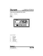
Страница 1: ...umber 57700 970 04 Durant Eclipse Series Ratemeter Process Timers Models 5770X 47X Table of Contents 1 Introduction 1 Description 5 Mounting 6 Wiring 11 Programming 16 Diagnostics 19 Specifications Vi...

Страница 2: ...t per minute barrels per hour etc or in units of time such as baking time or mold ma chine cycle time In either case the Eclipse employes the fiendishly clever Tau method of calculation which means th...

Страница 3: ...e input frequency at a steady speed The Eclipse has a programmable display update time that sets the minimum time between updates Each time the display updates the unit waits until the update timer ti...

Страница 4: ...a programmable value that is common to both setpoints and both relays This means that a relay turns OFF when the display is less than or equal to the high setpoint minus the hysteresis value or when t...

Страница 5: ...al serial communication board allows a host device to download and read programming parameters and to read status information from the rate meter such as display value relay status etc This manual doe...

Страница 6: ...body until adhesive surface makes contact with the front bezel 2 Slide unit into cutout in panel 3 Attach mounting clips and screws 4 Tighten screws until unit is firmly in place DO NOT OVERTIGHTEN sc...

Страница 7: ...ree additional circuit boards with headers may be installed These option boards are relay output RS 485 serial communications and analog retransmission The option boards occupy spe cific locations in...

Страница 8: ...onnecting device for the equipment Switches and circuit breakers in Europe must comply with IEC 947 Terminal Connector Ratings AC or DC Power Input Relay Output 10A 250VAC Wire size 12 24AWG 3 1mm2 0...

Страница 9: ...ernal Fuse 1 External Fuse Size U S European 2 AMP 50 V Time Delay T2A 50 V Time Delay 12 VA AC Power Input for AC powered models 57701 47X No Internal Fuse 1 Power In L1 85 265 VAC L2 47 63 Hz 20 VA...

Страница 10: ...Max Mag Pickup Source PNP 10 kHz Max Single Ended 12 VDC Out 75 mA Max See Specifications pages 17 18 for input impedances and threshholds Relay Output Option Board Typical Wiring Durant 1 Terminal De...

Страница 11: ...on Option Board Durant 1 485 485 Common To Host Serial Port Analog Output Option Board Durant 4 20mA 1 0 10 V Common 4 20mA 0 10 V Output Ratings 4 20 mA into 750 W Ohms maximum 0 10 V into 2500 W Ohm...

Страница 12: ...to its minimum values 0V and 4 mA regardless of the input signal To enter the program mode 1 Connect Program Enable input terminal to Ground Durant Jumper Terminals 1 and 2 1 2 3 4 2 Press and hold t...

Страница 13: ...1 The parameter name is displayed by pressing and holding the program key PGM 2 The value of the parameter is displayed by releasing the program key 3 While holding the program key PGM the unit scrol...

Страница 14: ...lowing list shows all programming parameter names the default value for each and the selection range for each A programmed unit may be restored to de fault settings by pressing both the program PGM an...

Страница 15: ...scaler here The de cimal point location on this screen was selected in the scaler decimal point parameter above Range 0 001 to 9999 Display update time Sets the minimum time in seconds between displa...

Страница 16: ...log output 10V and 20 mA Range 0 to 99999 Relay 1 High Alarm Setpoint Enter the rate or time at which relay 1 will turn on if the rate or time goes above this value Range 0 to 99999 Relay 2 High Alarm...

Страница 17: ...If subsequent errors occur the NOVRAM itself may have failed and the unit should be returned to the factory for repair An error message indicates that the calibration section of NOVRAM has been corrup...

Страница 18: ...program enable input to ground Durant Jumper Terminals 1 and 2 1 2 3 4 3 While holding both the right arrow key and the up arrow key turn unit power ON Durant Power In The program LED and all display...

Страница 19: ...splay shows software part number Right Arrow All display segments and the program LED turn off and the analog output goes to maximum value 20 mA and 10V Up Arrow Each display digit will turn on one at...

Страница 20: ...ric Strength 2300 VAC to signal inputs and relays 500 VAC to RS 485 and analog outputs HUMAN INTERFACE Display 5 digits Type 56 high seven segment red LED Indicator One red LED program calibration ind...

Страница 21: ...ogrammable Parity Even odd or no parity Address Range 00 to 99 decimal Protocol Opto 22 compatible Isolation Dielectric Strength 2300 VAC to signal inputs relays and AC power inputs 500 VAC to analog...

Страница 22: ...are or may be to any extent liable including without limitation penalties imposed by the Consumer Product Safety Act P L 92 573 and liability imposed upon any person pursuant to the Magnuson Moss War...

Страница 23: ...Durant 901 S 12th Street Watertown WI 53094 800 540 9242 920 261 4070 Fax 920 261 9097 www durant com...

Отзывы: