


Pub 49004
Effective 9/00
Page 5
Providing Control Power
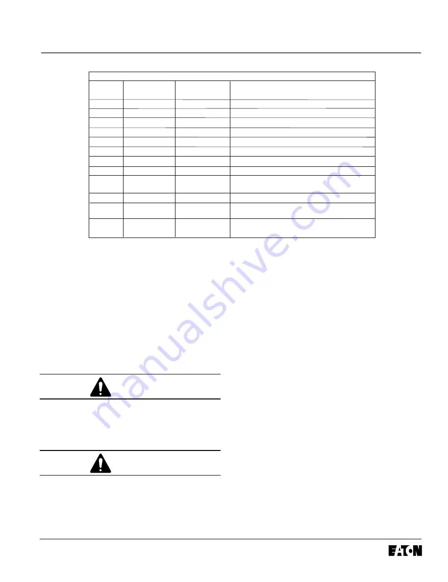
Name
Terminal Board
Default
Input
Designation
Common
-
-
Negative
Power
+
-
24VDC nominal
Permissive
P (24VDC only)
Hardwired Stop
24 VDC only
Input 1
1 (24VDC only)
Start
24VDC only
Input 2
2 (24VDC only)
Jog Forward
24VDC only
Input 3
3 (24VDC only)
Overload Disable
24VDC only
Input 4
4 (24VDC only)
Fault Reset
24VDC only
Common
13
-
Relay close connects to 14
NO Contact
14
-
3 Amps @ 120VAC/24VDC
in Bypass
10 Amps, Max (Resistive) Switching
Common
95
-
NC Connects to 96. Relay closure connects to 98.
Ready96
-
3 Amps @ 120VAC/24VDC
10 Amps, Max (Resistive) Switching
Fault
98
-
3 Amps @ 120VAC/24VDC
10 Amps, Max (Resistive) Switching
Control Wiring Inputs
13 and 14 - Closes when in bypass. Contact is normally open.
95 and 96 Close - System OK, Open Fault. Pins 95, 96, and
98 are Form C contact. 95 acts as the common, 96 is a normally
closed contact, and 98 is a normally open contact. On any
fault that trips the unit or causes it not to start, 96 opens and
98 closes.
95 and 98 Open - System OK, Close - Fault
95 and 96 Open - Fault
The control wiring is connected to the soft starter by a
12-pin terminal strip connector located on the front of the
unit. Each connection is capable of holding one or two
#22 - #16 AWG wires, or one #14 or #12 AWG wire.
Each terminal should be tightened to 3.5 in-lb.
APPLY ONLY 24VDC TO CONTROL TERMINAL
BOARD UNLESS SPECIFIED OTHERWISE IN THIS
MANUAL. ALL CONTROL WIRING IS 22 - 12 AWG.
FAILURE TO FOLLOW THIS CAUTION COULD RE-
SULT IN SEVERE DAMAGE TO THE CONTROLLER.
CAUTION
APPLIQUER UNE TENSION DE 24V C.C. AUX BORNES
SAUF AVIS CONTRAIRE DANS CE MANUEL. TOUTE
LA FILERIE DE COMMANDE EST DE CALIBRE 22 A
12 AWG. L’INOBSERVATION DE CETTE MESURE
POURRAIT CAUSER DES DOMMAGES IMPORTANTS
AU CONTROLEUR.
ATTENTION
1. Connect DC common (negative) to pin -.
2. C24VDC positive to pin +.
3. Pin P, permissive circuit, must be energized (+24VDC)
to allow operation of unit. If power is removed from
permissive circuit at any time, unit will initiate a stop.
4. If 24VDC power is toggled to Input 1 while P is at 24V,
device will initiate a start.
5. Input 2 is Forward Jog. If 24VDC power is applied to
Input 2 while P is at 24V, the soft starter will initiate
motor jog.
6. Input 3 is Overload Disable. When Input 3 is toggled,
the overload will be disabled for the next start.
7. If +24VDC input power is applied to Input 4, the soft
starter is reset. Faults are cleared only if fault has
been corrected.
8. Pins 13 and 14 - 120VAC or 24VDC provide for the
integral bypass contact. The integral bypass contact
will close upon bypass and will remain closed until
stop is initiated. Motor may continue to run even after
stop is initiated during soft stop until programmed
ramp has been completed.
9. Pins 95, 96, and 98 provide alarm circuit NO-NC
change state on any fault. Form C Max. 24VDC,
120VAC, 3 amps.
NOTE -
When control power (+24VDC) is first applied,
all the LEDs on the CIM will illuminate briefly. This is a
normal startup test that verifies communication to the
CIM. Pressing Fault Reset also momentarily lights all
the LEDs. This verifies the CIM board is functional, and
tests all LEDs for functionality.
Table 4
All manuals and user guides at all-guides.com


