DRAFT - 07 March 2016
DRAFT - 07 March 2016
INM MTL GECMA WS display rev 2
19
8 .6 Re-installing the GECMA COM module
The replacement of the COM module is effectively a reversal of the removal process.
1. Ensure the rear of the display module is cleared of any small items or contaminants
and the underside of the COM module is similarly clean before mounting the COM
module onto the six mounting studs attached to the rear of the display module.
2. Hold the COM module in position while fitting the six retaining nuts onto the studs and
tighten them to a recommended torque value of 2 Nm.
3. Re-attach the main COM Module earth cable to the COM Module earth stud and
tighten the retaining nut to a recommended torque value of 2 Nm.
4. Re-connect the Keyboard into the ‘KB’ connector and similarly any Pointing Device to
the ‘PD’ connector along with associated USB and RS232 connections.. Note that both
of these have retaining clips which will click into place when the connector is fully seated.
5. Re-connect the LVDS (Video) Signal cable into the ‘J302’ socket and re-attach its earth
cable to the LVDS Signal earth stud to ensure a good earth connection.
8 .7 Re-installing the MTL GECMA WS PSU module
The replacement of the PSU module is effectively a reversal of the removal process.
1. Ensure the rear of the display module is cleared of any small items or contaminants
and the underside of the PSU module is similarly clean before mounting the PSU
module onto the four mounting studs attached to the rear of the display module.
2. Hold the PSU module in position while fitting the four retaining nuts onto the studs and
tighten them to a recommended torque value of 2 Nm.
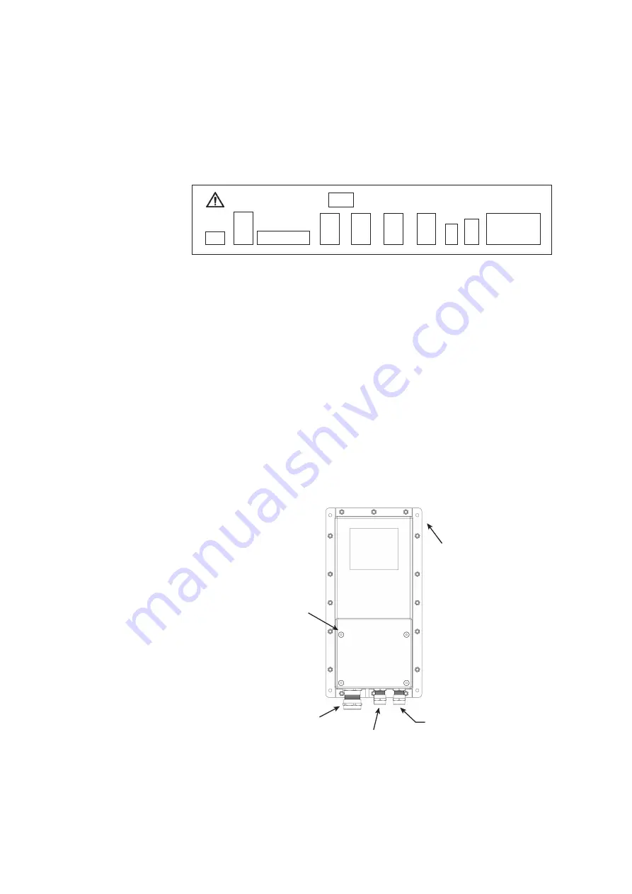
3. Loosen and remove the four screws (‘B’) shown that secure the terminal cover plate of
the PSU module and remove it.
SW501
J706
VIDEO
J302
USB1
J402
USB2
J403
USB3
J404
USB4
J405
KB
J503
PD
J703
RS232
J702
Fibre
Optic
Mounting stud
hole positions
‘A’ (x4)
Terminal
cover plate
fixing screws
‘B’ (x4)
Power in
COM power
Display power
A
A
A
A
B
B
B
B