Eaton CM52 Скачать руководство пользователя страница 9

9

Instruction Leaflet 

IL02401001E

Effective August 2009

CM52 Network Protector

with Arc Flash Reduction Module

EAtoN CoRPoRAtIoN www.networkprotectors.net

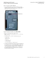
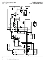
StEP 17 testing the CM52 ARM-IDM

A . Set the INCOM address on the CM52 ARM-IDM by using the 

two dials located near the top if the IDM .  It is important that this 

address be unique and has not been used on any other ARM-

IDM’s or MPCV relay (Refer to Figure 18) .

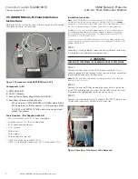
Figure 18. Location of the Dials on the CM52 ARM-IDM

B . Power up the breaker using a 3 phase test set . 

Note:

 For operation of the CM52 ARM-IDM to function, the MPCV relay 

must be connected .

C . The following LED’s must be illuminated upon power-up:

1 .  Power ON
2 .  Motor Enabled
3 .  Motor OK
4 .  Spring Release OK
5 .  IDM Trip Enabled
6 .  Unit Status (flashes at 1 second intervals)

D .  Enable the CM52 ARM-IDM, either with the communications link 

or a hard wired switch .  The Maintenance Mode LED should now 

be illuminated .  Once the actual current reaches between 2 .1 & 

2 .5 times the breaker CT rating, the Maintenance Mode Trip LED 

will be illuminated and the breaker will trip .   This rating of cur-

rent cannot be driven by the 3-phase test sets .  As long as the 

Maintenance Mode Trip LED is illuminated, the motor close of 

the network breaker is disabled .

Содержание CM52

Страница 1: ...ngs 2 3 Arming Maintenance Mode 2 4 Remote Indicator 2 5 Tripping and Testing 2 6 Wiring Diagram 3 7 ARM IDM Retro fit Field Installation Instructions 4 Effective August 2009 Instruction Leaflet IL024...

Страница 2: ...a fast acting response to the fault The reduced arc condition will occur only in devices downstream of the unit in Maintenance Mode The Maintenance Mode indicator LED is located in the upper portion...

Страница 3: ...Activation Relay The recommended selector switch for this low voltage application is Eaton part number 10250T1333 2E which includes a contact block rated for Logic Level and Corrosive use The maximum...

Страница 4: ...ration CM52 using the Voltage Regulator Device VRD as the breaker wiring is different from that of current production Installation of this kit should take approximately 2 5 hours Please refer to your...

Страница 5: ...ocking tab is engaged Figure 4 Wire Harness Labeled with Wire Numbers Figure 5 Correct Orientation for the IDM STEP 6 The 9 Wire Harness has an IDM terminal block attached Feed the wires with the term...

Страница 6: ...ER BOLTS STEP 11 WARNING Internal fuses and or external fuses and disconnect links MUST be removed prior to proceeding as the upper interphase barrier system must be removed For complete safety use an...

Страница 7: ...nd side sheet of the relay module by removing the protective paper covering the adhesive strips Figure 12 Location of the GAPs Module STEP 14 Connect the four point twist connector from the new second...

Страница 8: ...d remove the protective paper from the adhesive strip Locate the module such that the flying leads marked 1C 2C and 3C are as close as practical to the front edge of the DIN rail terminal block Refer...

Страница 9: ...or operation of the CM52 ARM IDM to function the MPCV relay must be connected C The following LED s must be illuminated upon power up 1 Power ON 2 Motor Enabled 3 Motor OK 4 Spring Release OK 5 IDM Tr...

Страница 10: ...10 Instruction Leaflet IL02401001E Effective August 2009 CM52 Network Protector with Arc Flash Reduction Module eaton corporation www networkprotectors net Figure 19 ARMS Schematic...

Страница 11: ...11 Instruction Leaflet IL02401001E Effective August 2009 CM52 Network Protector with Arc Flash Reduction Module eaton corporation www networkprotectors net Notes...

Страница 12: ...parties This literature is not intended to and does not enlarge or add to any such contract The sole source governing the rights and remedies of any purchaser of this equipment is the contract between...

Отзывы: