5
Instruction Leaflet
IL02401001E
Effective August 2009
CM52 Network Protector
with Arc Flash Reduction Module
EAtoN CoRPoRAtIoN www.networkprotectors.net
StEP 5
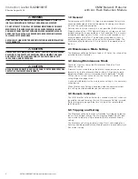
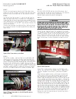
Apply the 3 Wire Harness labeled with wire numbers 1, 2, and 3 as
shown in Figure 4 . Note the difference in the connectors . The small
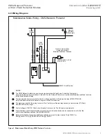
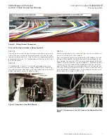
loop connector fits the IDM terminal block . Make certain that the
IDM contact is placed into the connector body in the correct orienta-
tion as shown below in Figure 5 with the locking tab of the contact
engaging the slot in the connector body . Give wires a slight pull to
ensure that the locking tab is engaged .
Figure 4. Wire Harness Labeled with Wire Numbers
Figure 5. Correct Orientation for the IDM
StEP 6
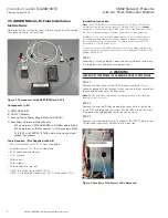
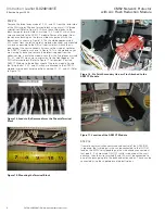
The 9 Wire Harness has an IDM terminal block attached . Feed the
wires with the terminal block down from the top of the plate . Affix
the terminal block to the lower cutout on the IDM mounting plate
with the wires routed on the back side of the mounting plate (Refer
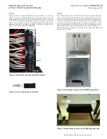
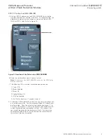
to Figure 6) . Note, the angled edge of the terminal block must face
down and the block must be inserted such that the dimples on the
mounting plate restrain the blocks movement (Refer to Figure 7) .
Make certain the twisted pair is located on the right hand side when
viewed from the front .
Figure 6. Terminal Block Affixed to the IDM Mounting Plate
Figure 7. Terminal Block position on the IDM Mounting Plate


