

3
Instruction Leaflet
IL02401001E
Effective August 2009
CM52 Network Protector
with Arc Flash Reduction Module
EAtoN CoRPoRAtIoN www.networkprotectors.net
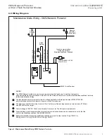
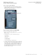
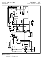
6.0 Wiring Diagram
Figure 1. Maintenance Mode Wiring CM52 Network Protector.
Maintenance Mode Wiring - CM52 Network Protector
Control
Voltage
4
5
L
3
Remote
Indicator
(Blue Light)
2
1
ARM
Switch
Incom communication
wiring can activate
Maintenance Mode if desired.
6
CM52 Circuit Breaker
NOTES:
The CM52 Network protector can be armed via a remote switch as shown. In addition, the function
can be activated via communications. A blue LED on the Network Protector unit verifies that Maintenance Mode is armed.
(AAR) Arms Activation Relay
The recommended selector switch for this low voltage application is Eaton part number #10250T1333-2E
which includes a contact block rated for Logic Level and Corrosive use.
The maximum length of this wiring to remote “Arm” switch (or alternate relay contact) is three meters (9.78 feet).
Use #20 AWG wire or larger.
Control voltage is 120VAC. Check circuit breaker front cover for Trip Unit power requirements.
A remote Stack Light, Annunciator Panel or other remote indication device can be connected to verify that the
unit is in the Maintenance Mode (Part #NAS0430G02).
Relay in PS Module closes when Maintenance Mode is armed. Contact is rated:1A @ 120VAC or
0.5A @ 230VAC or 1A @ 24-48VDC or 0.35A @125VDC.
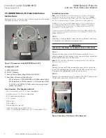
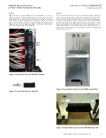
POINTS 3 & 4
1
INCOM WIRES ON TB3
M
O
C L
E
R
T
NI
O
P
S
P
C
AV
02
1
T
NI
O
P
S
P
LI
O
C
R
A
A
ML
A
M
M
T
NI
O
P
S
P
M
O
C
V
T
NI
O
P
S
P
2LI
O
C
R
A
A


