6
Instruction Leaflet
IL02401001E
Effective August 2009
CM52 Network Protector
with Arc Flash Reduction Module
EAtoN CoRPoRAtIoN www.networkprotectors.net
StEP 7
Re-attach the mounting plate using the four Phillips head screws,
making sure that the nine leads are routed out the top of the mount-
ing plate and are not pinched by the rear mounted terminal block .
StEP 8
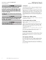
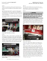
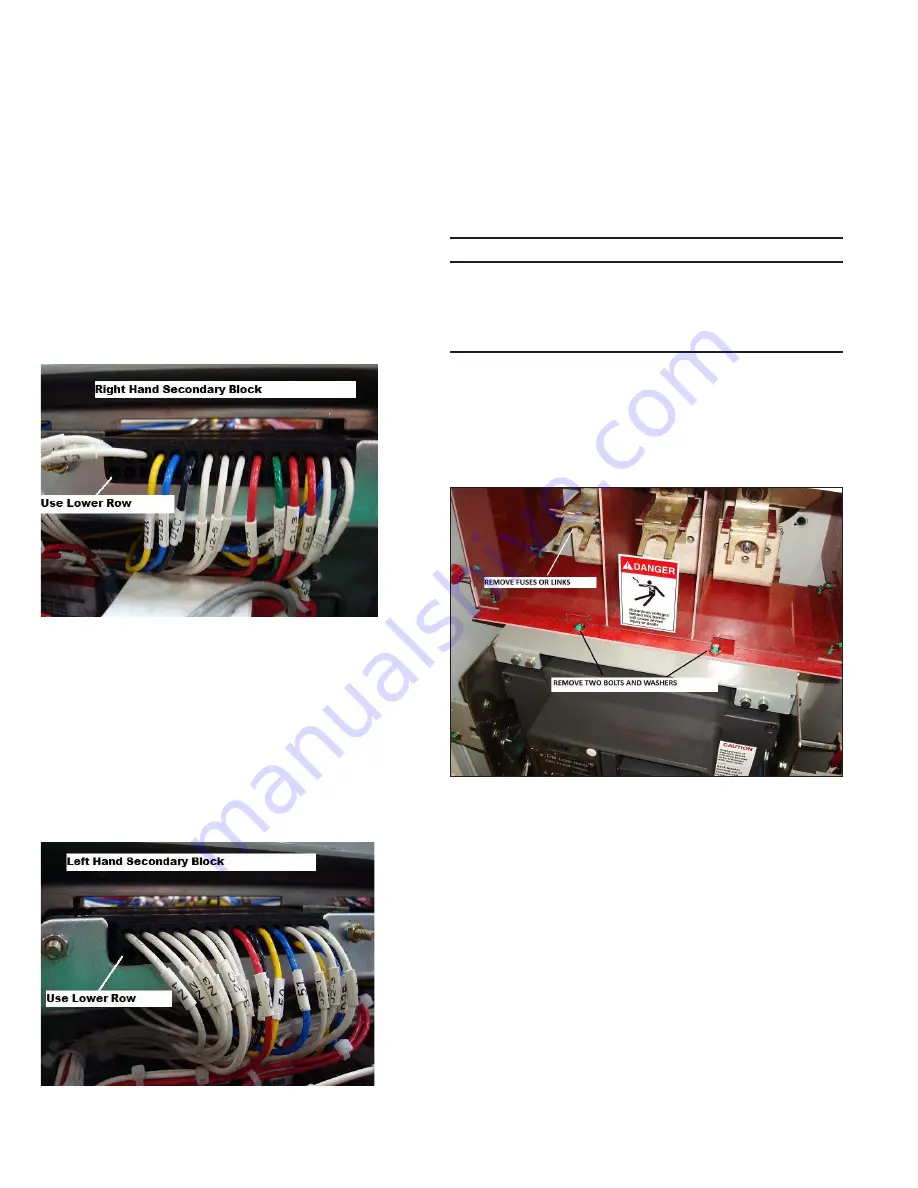
Connect the three wires marked 1, 2, and 3 to the right hand sec-
ondary disconnect block (ID’d as B secondary on wiring diagrams)
starting from the left with #1 . Note, these are connected on the left
hand side, bottom row of the block (Refer to Figure 8) . If you make a
mistake in pin location, use the AMP
E
extraction tool to remove the
contact from the block .
Once the wires have been inserted, give them a slight pull outward
to ensure that the terminal has been locked into the secondary dis-
connect block .
Figure 8. Wire Connections on the Block
StEP 9
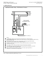
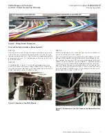
Connect the nine leads, which have been routing behind the IDM
mounting plate, to the left hand secondary disconnect block (ID’d
as A secondary on wiring diagrams) . Note, again these will be con-
nected starting on the left hand side, bottom row of the block (Refer
to Figure 4) . The left hand wire is marked I9 . They are inserted
from left to right—I9, I8, I7, I6, I5, I4, and I3, followed by the INCOM
twisted pair . There is no polarity to the twisted pair . Once the wires
have been inserted, give them a slight pull outward to ensure that
the terminal has been locked into the secondary disconnect block .
Figure 9. Wiring Connections on the Left Hand Secondary
Disconnect Block
StEP 10
Install the CM52 ARM IDM and then re-install the breaker front
cover . Remember to hold the manual charging arm in the complete
down position to facilitate the front cover placement .
DO NOT OVER TIGHTEN THE FRONT COVER BOLTS .
StEP 11
Warning
internal fuses and/or external fuses and disconnect links
must be removed prior to proceeding as the upper interphase
barrier system must be removed. for complete safety, use an
insulated blanket to prohibit frontal access to either the
transformer or netWork side bus Work. make certain that
the breaker remains in the disconnect position.
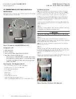
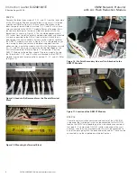
Remove the clear “dead front cover” by removing the four thumb
nuts . Remove the two bolts which are located on the top side of the
secondary disconnect bracket . The entire interphase barrier assem-
bly can slide forward and be set aside . See Figure 10 for location
of these two bolts . Once the interphase barrier has been removed,
blanket this entire bus structure to prevent an accidental short cir-
cuit .
Figure 10. Bolt Locations
Using a 7/16” wrench or socket, remove two 1/4-20 bolts, with
washers, from each side of the secondary contact support bracket
and rotate the bracket away from you . It should now be upside
down .
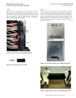
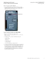
Taking the long secondary harness; carefully push the end of the
harness which has the 6 and 4 point connector, plus some flying
leads, through the wiring port on the left hand side of the relay
module . Taking the other end of the harness, which has the second-
ary pins attached; insert the harness as per Figure 11, starting with
wire I9 on the left hand block, left hand side and wire #1 on the right
hand block, left hand side . You will need a long pair of needle nose
pliers to aid in locating the pins into the secondary block . Note, you
will be using the top row locations of the secondary contact blocks,
since the entire secondary bracket has been turned upside-down .
The wires must run under the metal frame of the secondary bracket .
Once the wires have been inserted, give them a slight pull outward
to ensure that the terminal has been locked into the secondary dis-
connect block . Wire tie the new harness to the existing harness .
Rotate and re-attach the secondary contact bracket using the four
1/4-20 bolts with washers .


