background image

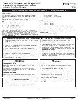
Champ® MLLA M2 Series Linear Emergency LED 

Luminaire Fittings for Hazardous Locations

Installation & Maintenance Information

SAVE THESE INSTRUCTIONS FOR FUTURE REFERENCE

IF 1946

IF 1946 • 09/22                                                         Copyright © 2022, Eaton’s Crouse-Hinds Division                                                                   Page 1

APPLICATION

CHAMP Linear Emergency LED luminaire are suitable for use in the following 

hazardous (classified) locations as defined by the National Electrical Code 

(NEC®):
The assembled luminaire shall be installed in accordance with the National 

Electric Code NFPA70, and American Bureau of Shipping.

NEC

• 

Class I, Division 2, Groups A, B, C, D

• 

Class I, Zone 2

• 

Class II, Division 1, Groups E, F, G

• 

Class III

• 

Wet location, IP66/67, Type 4X

These luminaire housings shall be used with UL listed Crouse-Hinds hazard-

ous locations luminaire fittings namely LED Light Engine Cat Nos. MLLA*2 or 

MLLA*4 series ending with M2 and Mounting means Cat Nos. M2-FLUSH- 

MT-KIT, M2-CEILING-SWIVEL-KIT, M2-CEILING-WALL-KIT, M2-PM-KIT-1.25, 

M2-PM-KIT-1.5, M2-PM-KIT-2.0, (refer to label provided inside the driver housing 

for permissible fitting details).

UL Standards:

• 

UL844 Hazardous (Classified)

• 

UL1598 Luminaires, UL1598A Marine

• UL8750
• UL924

CSA Standard:

• 

CSA C22.2 No. 250

• 

CSA C22.2 No. No.137

• 

CSA C22.2 No. No.141

Refer to the luminaire fitting nameplate for specific classification information, 

maximum ambient temperature suitability, and corresponding operating 

temperature (T-code).
The assembled linear LED luminaire is designed for use indoors and outdoors 

in marine and wet locations, where moisture, dirt, corrosion, vibration and 

rough usage may be present.

INPUT VOLTAGE:

• 

UNV1: 120-277 VAC 50/60 Hz

1.  Read carefully before installing and wiring luminaire and retain for future 

reference. 

2.  Ensure area to be free of hazardous atmospheres before and during 

installation and maintenance.

3.  Do not use accessory equipment not recommended by manufacturer 

may cause an unsafe condition.

4.  Use only replacement parts from Eaton’s Crouse Hinds division.
5.  To avoid the risk of fire, explosion or electric shock, this product should 

be installed, inspected and maintained by a qualified electrician only, in 

accordance with all applicable electrical codes.

6.  Do not use this equipment for other than intended use.
7.  Replace entire battery unit and LED driver when necessary. Contact the 

manufacturer for information on service. 

8.  Do not attempt to service battery.

9.  See product label for minimum supply wire temperature rating. 
10.  Battery requires 24hrs to fully charge. Allow 24 hours charging time 

before depending on the battery to operate at full capacity. 

11.  The emergency battery requires a minimum charge time of one (1) hour 

before testing the circuit, 24 hours is required for a full charge. 

12.  Equipment should be mounted in locations and at heights where it will 

not readily be subjected to tampering by unauthorized personnel. 

Max. 

mounting height: 25.2 feet)


13.  The emergency luminaire is intended to be installed with CG-256 (issued 

by the American Bureau of Shipping and Coast Guard.

14.  This product must be installed in accordance with the applicable installa-

tion code by a person familiar with the construction and operation of the 

product and the hazards involved.

IMPORTANT SAFEGUARDS - READ AND FOLLOW ALL SAFETY INSTRUCTIONS

STORAGE INSTRUCTIONS

1. 

EM luminaire must be stored in an ambient temperature range of 0°C 

to 40°C.

2. 

Battery should be charged and discharged within 6 months. At a 

minimum, the battery should be recharged within this time.

WARNING

To avoid electric shock:

Be certain electrical power is OFF before and during installation and 

maintenance.

Luminaire must be supplied by a wiring system with an equipment 

grounding conductor in accordance to the NEC and CEC for the specific 

Hazardous Locations involved.

To avoid burning hands: 

Make sure lens and housing are cool when performing maintenance.

!

WARNING

To avoid explosion: 

Make sure the supply voltage is the same as the luminaire voltage.
Do not install where the marked operating temperatures exceed the 

ignition temperature of the hazardous atmosphere.
Do not operate in ambient temperatures above those indicated on the 

luminaire nameplate.
Use proper supply wiring as specified on the luminaire nameplate.
All gasket seals must be clean and undamaged.
Before opening, electrical power to the luminaire must be turned off. 

Keep tightly closed when in operation.
To reduce the risk of ignition due to electrostatic discharge, avoid contact 

with the luminaire while explosive atmosphere is present. Clean only with 

damp cloth.

!

Содержание Champ MLLA M2 Series

Страница 1: ...6 Do not use this equipment for other than intended use 7 Replace entire battery unit and LED driver when necessary Contact the manufacturer for information on service 8 Do not attempt to service bat...

Страница 2: ...ASSY2 CAT2 CAT1 ASSY1 ARE IN MILLIMETERS DIMENSIONS IN ARE IN ALL PRIMARY DIMENSIONS UNLESS OTHERWISE SPECIFIED MM DD YYYY Your Name WITH ASME Y14 5 2009 DIM AND TOL IN ACCORDANCE 1 3 INCHES rev 0000...

Страница 3: ...AND TRADE SECRET INFORMATION POSSESSION DOES NOT CONVEY ANY RIGHTS TO LOAN SELL OR DISCLOSE SAID INFORMATION REPRODUCTION OR USE FOR ANY PURPOSE OTHER THAN WHICH IT WAS SUPPLIED MAY NOT BE MADE WITHOU...

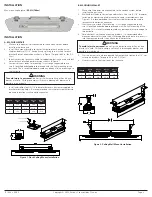
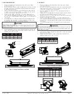
Страница 4: ...d of the support cable to one of the four 4 attachment points provided on the luminaire driver housing and secure the other end to a fixed support Use a minimum of two 2 support cables per luminaire s...

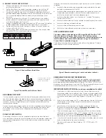
Страница 5: ...ed conduit is torqued to 42 52 ft lbs 57 71 N m for 3 4 plug 4 Verify supply wires are connected to luminaire wire leads per Figure 14A Figure 14B or Figure 14C 5 Verify all electrical connections are...

Страница 6: ...Figure 14A 2 Foot UNV1 Standard Wiring Diagram Figure 14B 4 Foot UNV1 Standard Wiring Diagram WIRING DIAGRAMS IF 1946 09 22 Copyright 2022 Eaton s Crouse Hinds Division Page 6...

Страница 7: ...eck to make sure that all connections are clean and tight 7 Mechanically check that all parts are properly assembled 8 Check and re torque all mounting hardware 9 To prevent heat build up remove dust...

Страница 8: ...sea necesario Comun quese con el fabricante para recibir informaci n acerca del servicio 8 No intente realizar el mantenimiento de la bater a 9 Consulte la etiqueta del producto para conocer la especi...

Страница 9: ...T2 CAT1 ASSY1 ARE IN MILLIMETERS DIMENSIONS IN ARE IN ALL PRIMARY DIMENSIONS UNLESS OTHERWISE SPECIFIED MM DD YYYY Your Name WITH ASME Y14 5 2009 DIM AND TOL IN ACCORDANCE 1 3 INCHES rev 0000000 WT 15...

Страница 10: ...ICH IT WAS SUPPLIED MAY NOT BE MADE WITHOUT EXPRESS WRITTEN PERMISSION OF EATON THIS DRAWING IS ON LOAN AND IS TO BE RETURNED UPON REQUEST Title Line 2 Your Name MM DD YYYY 1 5 005 01 ANGLES XXX XX X...

Страница 11: ...ta del controlador de la luminaria Coloque los cables de soporte secundarios de modo que se limite la distancia vertical suspendida a no m s de 18 pulgadas desde la posici n de montaje primaria Se deb...

Страница 12: ...recomienda aplicar aproximadamente 1 8 in de gotas de lubricante para roscas STL de Eaton en las entradas de conducto 3 Verifique que el conducto instalado est apretado con un torque de 42 52 ft lb 57...

Страница 13: ...DE PLACA DE CIRCUITO IMPRESO DE LED CONTRO LADOR L NEA NEUTRO A TIERRA L NEA NEUTRO A TIERRA CONECTOR DE LUMINARIA WAGO CN2 L NEA NEUTRO A TIERRA LED LED TENUE TENUE INDICADOR DE CARGA MONTAJE REMOTO...

Страница 14: ...cubierta LED con un cepillo suave o presi n de aire 10 Inspeccione visualmente la luz indicadora de estado de carga una vez al mes Debe estar encendida cuando la alimentaci n de CA est activa Si el in...

Страница 15: ...mble de la batterie et du circuit de commande de DEL si n cessaire Communiquer avec le fabricant pour obtenir des renseignements sur le service 8 Ne pas essayer de faire un entretien de la batterie 9...

Страница 16: ...T1 ASSY1 ARE IN MILLIMETERS DIMENSIONS IN ARE IN ALL PRIMARY DIMENSIONS UNLESS OTHERWISE SPECIFIED MM DD YYYY Your Name WITH ASME Y14 5 2009 DIM AND TOL IN ACCORDANCE 1 3 INCHES rev 0000000 WT 15 84 L...

Страница 17: ...ANY PURPOSE OTHER THAN WHICH IT WAS SUPPLIED MAY NOT BE MADE WITHOUT EXPRESS WRITTEN PERMISSION OF EATON THIS DRAWING IS ON LOAN AND IS TO BE RETURNED UPON REQUEST Title Line 2 Your Name MM DD YYYY 1...

Страница 18: ...bles de support par luminaire en fixant un seul c ble deux 2 emplacements sur l ext rieur du bo tier du pilote du luminaire Disposer les c bles de support secondaire de fa on limiter la distance vert...

Страница 19: ...lets STL d Eaton d environ 1 8 po sur les orifices d entr e de conduit 3 V rifier que le conduit install est serr un couple de 42 52 pi lb 57 71 N m pour un bouchon de 3 4 po 4 V rifier que les fils d...

Страница 20: ...CCI DE DEL LIGNE NEUTRE MISE LA TERRE LIGNE NEUTRE MISE LA TERRE CONNECTEUR POUR LUMINAIRES WAGO CN2 LIGNE NEUTRE MISE LA TERRE DEL DEL GRADATEUR GRADATEUR VOYANT DE CHARGE MONT DISTANCE FOURNI PAR LE...

Страница 21: ...comprim 10 Inspecter visuellement le t moin d tat charge une fois par mois Il devrait tre allum lorsqu aliment en c a Si le voyant clignote communiquer avec le soutien technique 11 Tester le fonctionn...

Отзывы: