


29
Technical Data
PR202-50-502-22
Effective June 2017
CF2000 System
EATON
www.eaton.com
Protocol Format
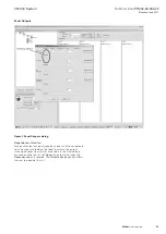
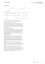
Figure 8. Full Protocol Format (not including repeaters)
Normal Communications to Devices
With the command bits set for the 'Normal' command and the
MSB of the three mode bits set at 0, this shortened version of the
Normal communications to each device allows the analogue reply
or status from each device to be read . This format of communica-
tion is generally used throughout all background supervision of the
addressable loop .
Alarm Interrogate Command
This command is seen by all devices on the loop, so no address
byte is required, and is periodically sent out during normal commu-
nications . This command allows any device experiencing an alarm
condition to respond, with call points given the highest priority,
reporting their address . This causes the control panel to break off
from general background supervision of the loop and focus directly
on the device in question .
Full Protocol Format
With the command bits set for the 'Normal' command and the
MSB of the three mode bits set at 1, the long version of the
Normal communications can be sent to any device . This would
normally be done by the panel following a response to the Alarm
Interrogate command, allowing the panel to check the device
address, ID and confirm that the analogue reply, or status, is truly
an alarm condition before actioning the panel sounder outputs, for
example .
Viewing the Voltage and Current waveforms at the panel
Loop 1: Using a Digital Storage Oscilloscope, connect one channel
to R84 on the Loop Driver Card; probe 0V clip to the 'Bottom' side
of the resistor; I/P to the 'out-board' side . This will display the loop
current .
Connect the other channel to Loop 1, S+ terminal on the main
mother board . DO NOT connect the 0v clip of this probe .
Loop 2: Using a Digital Storage Oscilloscope, connect one channel
to R82 on the Loop Driver Card; probe 0V clip to the 'Bottom' side
of the resistor . This will display the loop current . Connect the other
channel to Loop 2, S+ terminal on the main mother board . DO
NOT connect the 0v clip of this probe .


