


21
Technical Data
PR202-50-502-22
Effective June 2017
CF2000 System
EATON
www.eaton.com
Installation
Mains Supply
The mains supply must be installed in accordance with the current
edition of the IEE wiring regulations, and must be fully compliant
with local regulations .
Connection to the mains supply must be via an isolating device
(e .g . a double pole isolating fuse rated at 2A) reserved solely
for the fire alarm system . The cover should be coloured red and
labelled
FIRE ALARM - DO NOT SWITCH OFF
The isolating protective device should be secure from unauthor-
ised operation and ideally installed in a securely closed box with a
breakable cover .
An additional warning label should be provided, depending on
whether:
A.
The isolating protective device is fed from the live side of the
main isolating device in which case the label on the isolating
protective device, should read in addition:
WARNING: THIS SUPPLY REMAINS LIVE WHEN THE MAIN
SWITCH IS TURNED OFF
A further label should be placed on the main isolating device
reading
WARNING: THE FIRE ALARM SUPPLY REMAINS LIVE
WHEN THIS SWITCH IS TURNED OFF
Or
B.
If the isolating protective device is fed from the dead side of
the main isolating device, a label should be fixed to the main
isolating device reading
WARNING: THIS SWITCH ALSO CONTROLS THE SUPPLY
TO THE FIRE ALARM SYSTEM
Cable Segregation
All cables for the fire alarm system should be segregated from any
other cables/wiring/services .
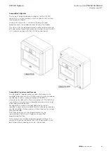
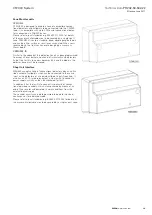
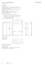
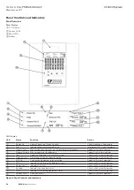
Panel Installation
The panel should be installed in a clean, dry, reasonably well
ventilated place, and not in direct sunlight . Temperatures in excess
of 40°C and below 5°C may cause problems, if in doubt consult
Cooper Fire Systems . The panel should be located away from
any potential hazard, in a position where it is readily accessible to
authorised staff, and the fire services, ideally on the perimeter of
a building near a permanent entrance . Mount the panel to the wall
using the drill template provided . Do not drill through the panel to
the wall as dust will contaminate the circuitry .
Installation Guide
•
Never carry out insulation tests on cables connected to elec-
tronic equipment .
•
DO NOT OVER TIGHTEN TERMINAL CONNECTOR SCREWS
•
Always use the correct type of cables specifically designed for
the operation of fire detection and alarm circuits .
•
Always adhere to volt drop limitation when sizing cables .
•
Always observe polarity throughout . Non colour coded conduc-
tors should be permanently identified .
•
Screen continuity must be maintained throughout the entire
loop circuit including at each junction point and at each device .
Terminals are provided on each device to facilitate this .
•
The screen should be earthed at the connection point provided
at the CF2000 panel and not at any other point . Both the loop
start and the loop end must be connected to the appropriate
earthing points .
•
Care must be taken to avoid connecting the screen to the
earthed body of any metal devices, enclosures or cable contain-
ment . The screen or drain wire of the loop cables should not
be considered as safety earth and therefore should not be
connected to terminals marked with the earth symbol, except
at the panel, and should not be insulated with green and yellow
sleeving .
•
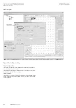
CF2000 utilises intelligent soft addressing technology to greatly
simplify the installation and commissioning processes . Once
the system has been installed and the loops wired to the panel
with all devices fitted, the CF2000 control panel will automati-
cally scan the detection loops on power up and allocate each
device with an address number corresponding with its posi-
tion on the loop . This avoids the traditional need for manual
addressing of the system devices which is time consuming and
provides a potential for error . If no devices can be found the
panel will keep rebooting and performing an auto-learn until a
device is found on a loop .
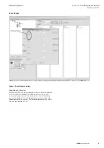
•
It is of vital importance that accurate details are kept of the
exact wiring route in order to determine which address has
been allocated to each device .


