WCB 11060 (PDF Format)
14
© Copyright Eaton Corp., 1998. All rights reserved
June, 1998
Read these instructions thoroughly
and review until you fully understand
the parts replacement steps before
proceeding with the work
described in this section. Failure to
follow these instructions can result
in unreasonable exposure to hazard-
ous conditions or personal injury.
4.1
Wear Adjustment
4.1.1
Single disc WCB’s
Note: Item numbers (#) are shown on
Figure 1.
4.1.1.1
There is no adjustment for single disc
elements. When the pressure plate (13)
bottoms against the stop tubes (59), replace
friction material and inspect wear plates for
wear. See section 6.0.
4.1.2
Dual, Triple & Quad disc WCB’s
Note: Items (#) referenced in Figures 2 & 3.
4.1.2.1
Dual disc elements have one adjustment,
triple disc elements have two adjustments
and quad disc elements have three adjust-
ments. Follow the wear spacer adjustment
procedures in section 4.1.3 for each adjust-
ment made.
4.1.3
Wear adjustment procedures (Multi disc)
Note: Item numbers (#) are shown on
Figures 2, 3 and 4.
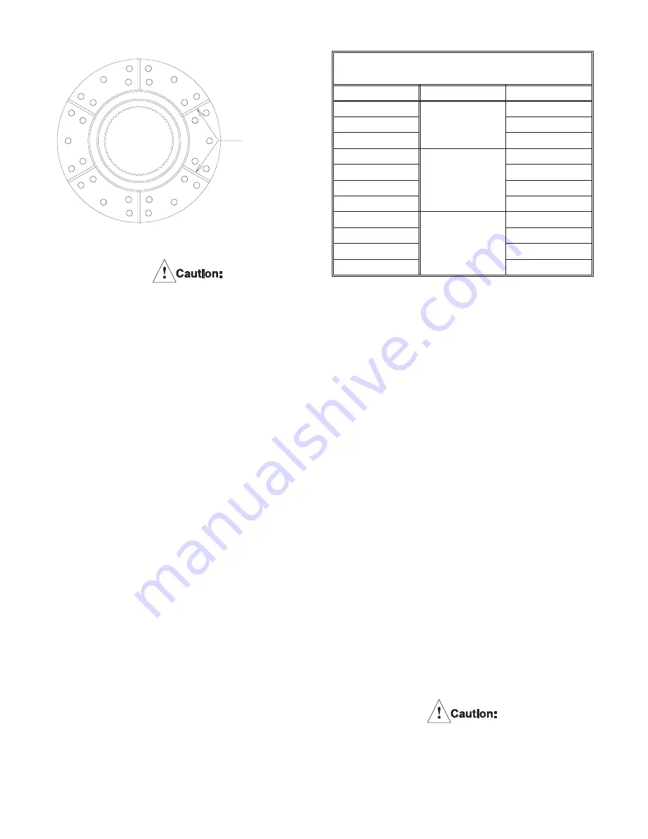
Note: On all units, the friction material must
be replaced when worn to the bottom of the
groove on the friction lining. See Figure 8.
See Table 17 in Section 6.0 for new wear
groove depth.
4.1.3.1
Disconnect air and water supply lines from
the tensioner.
4.1.3.2
While supporting the cylinder (19), loosen
the locknuts (18) ONE TURN AT TIME and in
an alternating (crosswise) pattern until the
spring force is completely relieved. Remove
the locknuts and washers (17). Mark all of
the water outlet ports for identification. Deep
well sockets are required. See table 10 for
size and depth of socket required.
4.1.3.3
Using lifting equipment, carefully remove
the cylinder (19) and piston (33) as an
assembly. Set aside in a clean area.
(Piston side up.)
Note: If a stud (6) should happen to come
loose, remove it completely, clean the
threads on the stud and the threads in the
mounting flange. Apply Locquic
®
Primer
Grade “T” to the stud threads. After the
threads have dried, assemble to the mount-
ing flange using Loctite
®
#262. The end of
the stud must not extend past the mounting
surface of the mounting flange.
Loctite
®
#262 must be shaken prior
to application.
Wear
Grooves
Figure 8
Table 10
Socket size and depth
Model
Nut Size
Socket Depth
118
1 1/16"
1 3/4"
218
2 3/8"
318
2 1/4"
124
1 /5/8"
1 3/4"
224
2 1/4"
324
6 5/8"
424
7 1/8"
136
2"
3 1/4"
236
4"
336
5 1/2"
436
6 1/5"


