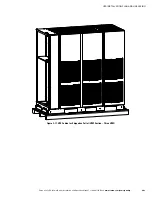
UPS INSTALLATION PLAN AND UNPACKING
Eaton 9395 UPS (450–825 kVA) Installation and Operation Manual
S
164201725 Rev 4
www.eaton.com/powerquality
3-28
S
The REPO switch wiring must be in accordance with NEC Article 725 Class 2
requirements.
S
The maximum distance between the REPO and the UPS cannot exceed
150 meters (500 feet).
S
Alarm relay contacts have a maximum current rating of 5A and a switched voltage
rating of 30 Vac and 28 Vdc.
S
Alarm relay wiring should be a minimum of 22 AWG.
3.2.4
Distributed Bypass Power Wiring Preparation
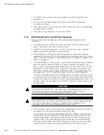
Read and understand the following notes while planning and performing the
installation:
S
All distributed bypass UPS rectifier inputs must come from one source and all
bypass input feeds must come from one source.
S
All UPSs in the distributed bypass system must contain the same number of
UPMs. Mixed UPS kVA ratings are not permitted.
S
Distributed bypass UPS input wiring size requirements and output wiring size
requirements from the UPSs to the tie cabinet or distribution panel are the same as
listed in Table 3‐4 on page 3-14, Table 3‐5 on page 3-15, Table 3‐6 on page 3-16, or
Table 3‐7 on page 3-17.
S
If the load requires a neutral, a bypass source neutral must be provided. If the load
does not require a neutral and there is no neutral conductor connected at the
bypass input, a neutral to ground bonding jumper must be installed. Install neutral
conductors from the UPSs to the common point of connection (tie cabinet), and
then install a system neutral to ground bonding jumper. The bonding jumper must
be copper wire. DO NOT install both a source neutral and a bonding jumper.
If the recommended system neutral bonding jumper installation method cannot be
accomplished, each UPS should have a separate neutral to ground bonding jumper
installed. See Table 3‐4 or Table 3‐5 for UPS neutral bonding jumper wire sizes. The
bonding jumper must be copper wire. DO NOT install both a source neutral and a
bonding jumper.
C
A
U
T
I
O
N
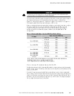
HIGH IMPEDANCE GROUND SOURCES - If the supply source is a high impedance ground (IT) type, the
neutral‐forming transformer kit must be used instead of pulling a neutral from the source. In no
circumstances shall a neutral to ground bonding jumper be installed in the UPS.
C
A
U
T
I
O
N
DELTA SOURCES (TN‐S) - The UPS cannot be operated from a mid‐point or end‐point grounded delta supply
source. With this type of supply source, there is no capability to provide an output neutral. In no
circumstances shall a neutral to ground bonding jumper be installed in the UPS.
S
MOBs with dual auxiliary contacts are to be supplied by the customer. Table 3‐18
on page 3-25 lists the recommended rating for the MOBs.
The tie cabinet must contain Module Output Breakers (MOBs) with dual auxiliary
contacts for control of the system. Without dual auxiliary MOBs, UPMs are not
allowed to go to bypass individually during servicing. All UPMs will go to bypass
instead of the just the UPM needing service, decreasing critical load protection.
With dual auxiliary MOBs, one UPM can be bypassed while the remaining UPMs
support the load as long as the remaining UPMs have the capacity to do so.
Содержание 9395 UPS
Страница 2: ......
Страница 28: ...Eaton 9395 UPS 450 825 kVA Installation and Operation Manual S 164201725 Rev 4 www eaton com powerquality 2 2...
Страница 134: ...Eaton 9395 UPS 450 825 kVA Installation and Operation Manual S 164201725 Rev 4 www eaton com powerquality 5 20...
Страница 254: ...WARRANTY Eaton 9395 UPS 450 825 kVA Installation and Operation Manual S 164201725 Rev 4 www eaton com powerquality W 2...
Страница 255: ......
Страница 256: ...1642017254 164201725 4...


