EASY-BUILD DERBY LIGHTWEIGHT CLASS 108 DMU Скачать руководство пользователя страница 9

LEAVE BODY TO HARDEN

33)

Once the roof has firmly set, take time now to inspect the fit of the roof outline against the

end molding. Due to the different means by which the roof and ends are produced, it will be found
that the alignment of the roof line and the ends requires blending with an appropriate car body, or
modelling filler. Likewise, there is a gap between the underside of the roof and the top of the non-cab
ends which also requires filling as necessary.

Once again, do take your time with these steps not least because the roof and end joints will be very
visible on the finished model.

34)

If the roof vents were not fitted earlier now is the time to do so. The roof vents will also offer

the body some extra stability when it is placed upside-down for the following steps.

35)

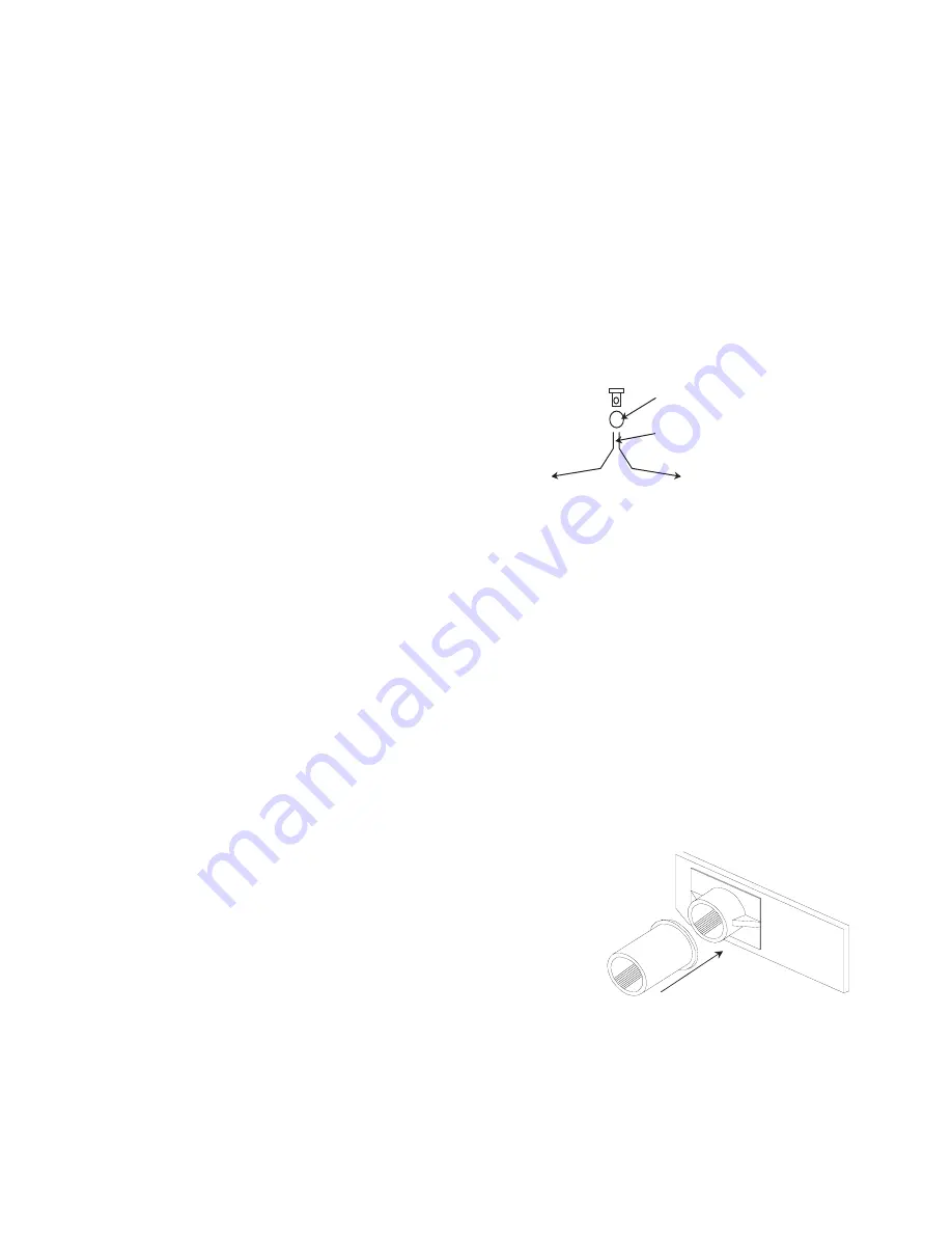
(DMCL) Form and fit the water pipes to the filler casting (unfortunately not shown on the

castings photo, but looks like a small top hat!) on the roof
and down to the brackets moulded onto the end. Use
0.7mm brass wire for the pipes, file the ends of the two
halves flat, solder together, drill a hole through the body of
the filler and insert the pipe end. See photos for shape of
pipe run (DMBS GUARDS DOOR - Cl. 108 prototype). Cut off the pipes about 2.5mm below the
retainers.

36)

(DMCL) Fit the small roof box (C33) detail on the centerline between the second pair of vents

(from the rear).

UNDERFLOOR ASSEMBLY

NOTE: The molded ribs on the floor molding determine the underside of the floor molding!

37)

Check the floors will fit within the sides and end molding. It is likely that you will have to adjust

the floor width to gain the best fit. Do this carefully removing the minimum amount evenly from each
side to keep the floor central to the body. This is best done using a scraping action with a sharp blade.

38)

To improve the visual appearance of the underframe, cut the two lengths of 5mm wide 0.5mm

styrene to 391mm and affix to the outside face of the molded solebars. Align the strips to the rear
edge of the underfloor so that they protrude at the front (take care when handling so as not to break
the ends). Keep the strip firmly butted against the underside of the floor lip.

39)

Remove the four bufferbeams from their sprues together

with their associated extension collars, clean flash, etc. and check
the fit of the buffer shanks into the holes. Use a 3mm drill bit to
carefully open any tight holes to allow the buffers to slide easily. Use
a buffer to align the buffer stock extension collar to the end of the
buffer housing - affix with solvent and remove the buffer
immediately. Once the joints have hardened run the 3mm drill
through again to ensure the holes are clean.

40)

Install the floor into the body and temporarily secure into position. Now fit the bufferbeams to

the underside of the cab ends, aligned centrally across the cab and butted against the ends of the
extended solebars to ensure vertical squareness. 

DO NOT GLUE THE BUFFERBEAM TO THE

SOLEBAR EXTENSIONS BECAUSE IF YOU DO, YOU WILL NOT BE ABLE TO REMOVE THE

9

DRILL 0.7MM HOLE THROUGH
BODY OF FILLER
FILE HALF FLAT BETWEEN
TWO PIPES AND SOLDER
TOGETHER

Buffer

Extension

Содержание DERBY LIGHTWEIGHT CLASS 108 DMU

Страница 1: ...will also find numerous additional prototype and model images to assist you create an outstanding model GETTING STARTED The basic steps are the same for both car types so unless there is an operation...

Страница 2: ...ype without the butterfly mounting part E11 It is probably unusual for this arrangement to have survived throughout the unit s working life so if possible check photographs of your chosen unit before...

Страница 3: ...es not need marking because the motor cut out in the floor makes orientation obvious 13 Check the floor molding for flatness if it appears too distorted some curvature is quite normal gently bend it i...

Страница 4: ...should now be drilled out as required No provision is made for this in the kit and so it is up to the builder to determine how best to achieve the installation NON CAB ENDS PREP These are our standard...

Страница 5: ...it but not sloppy if necessary clean hole with a 2 5mm drill Do not fix in position as adjustments will be made later 28 3 Using a pin add a tiny drop of oil NOT WD 40 into the bearing surface 28 4 Pl...

Страница 6: ...ogie stretcher While the basic bogie assembly sets identify and remove the bogie front channel guard irons speedo drive mount and bogie steps from the etched sheet 28 14 Fold up the bogie channels E3...

Страница 7: ...is might need further adjustment later on 29 5 Bolt one sideframe assembly to the bogie stretcher plate with 2x 2mm nuts and bolts provided 29 6 Insert the wheelsets into the assembly ensuring the set...

Страница 8: ...mm x 0 7mm 30 thou step treads and fix to the step supports as required BODY ASSEMBLY CONTINUED NOTE BEFORE PROCEEDING MAKE SURE YOU HAVE GOT THE CORRECT ROOF AND BODY PAIRED TOGETHER DMBS WITHOUT WAT...

Страница 9: ...loor molding 37 Check the floors will fit within the sides and end molding It is likely that you will have to adjust the floor width to gain the best fit Do this carefully removing the minimum amount...

Страница 10: ...U cables some method of attaching cables is necessary if not the castings can simply be fitted as is with the exception of C1d which should always be prepared as described 43 1 After cleaning up the c...

Страница 11: ...connection the final position being approximately as shown right The bottom mounting bracket should be 17mm from the bottom of the end 48 Decide whether to fit the small destination box C6 or the larg...

Страница 12: ...90o and fix solder glue into the half etch pads in the rear cab walls so that the folded projection forms a slot with the fold at the bottom of the cab partition See photo Partition with floor support...

Страница 13: ...See photo mid body strengthener and cab walls Cl 129 model for this additional much wider support as used on the Cravens Class 129 54 Cut a piece of 1mm 40 thou styrene 15mm wide to fit between the mo...

Страница 14: ...le assemblies have been mounted the exhaust stub on the diesel engines can be soldered or glued to the rear of the exhaust flexible canister the round cylindrical bit to give extra support to the exha...

Страница 15: ...e installing the etched window frames check the fit of the window glazing within the openings Carefully file the edges of the glazing panels until they fit snuggly but not sloppy nor tight Using a slo...

Страница 16: ...floor to be fitted Paint and fit toilet cubicle as appropriate FINAL ASSEMBLY 69 Find the windscreens you put in a safe place some time ago and fit using small amounts of adhesive If you have some RC...

Страница 17: ...and secure as before 79 Assemble the underframes onto the appropriate bodies and secure in place 80 Mount the bogies and ensure they are free to rotate The speedo drives can be connected to the soleba...

Страница 18: ...mm taken from rear of roof 99 8 8 237 21 Water filler DMCL only 46 5 DMBS BAGGAGE AREA ABS DIVIDER PARTITION WITH DOOR SEATING ARRANGEMENTS SHOWING FACING DIRECTION HALF PARTITIONS DMCL DTCL PARTITIO...

Страница 19: ...4 C15 C32 C13 C26 C30 C27 225mm 235mm 242mm 249mm C30 C31 C26 C13 C23 C19 C14 C11 C24 C15 C32 C13 C29 E8 C22 C25 C10 C17 C13 C18 C26 C31 100mm 104mm 132mm 146mm 156mm 181mm 203mm 220mm 230mm 242mm 245...

Страница 20: ...20 DMBS DMCL CASTINGS CONTROL DESK DETAILS...

Страница 21: ...EIVER BACKING for small casting C6 E14 SPEEDO SENDER BACKING for large casting C6 E15 LARGE HEADCODE BOX E16 LARGE HEADCODE BOX FRONT E17 LAMP IRONS E18 BRAKE WHEELS E19 2 DIGIT HEADCODE FRAME E20 HEA...

Страница 22: ...o with the round aluminium mounting is securely in place as described in the main text file or cut off the edge of the floor motor opening and mounting sufficiently to allow the motor to move through...

Отзывы: