To order parts and supplies: 800.343.9353 >> eastwood.com
13
SET-UP THE MIG 90 FOR FLUX CORE WELDING
The Eastwood MIG 90 comes factory set-up to weld with Solid Wire and Shielding Gas.
Flux Core does not require shielding gas.
Three changes to the Set-Up need to be made to MIG Weld with Flux Core wire:
- Reverse polarity from DCEP to DCEN.
- Install Flux Core wire.
- Position Drive Roller to accept Flux Core wire.
CHANGING THE POLARITY TO DCEN FOR WELDING WITH FLUX CORE WIRE
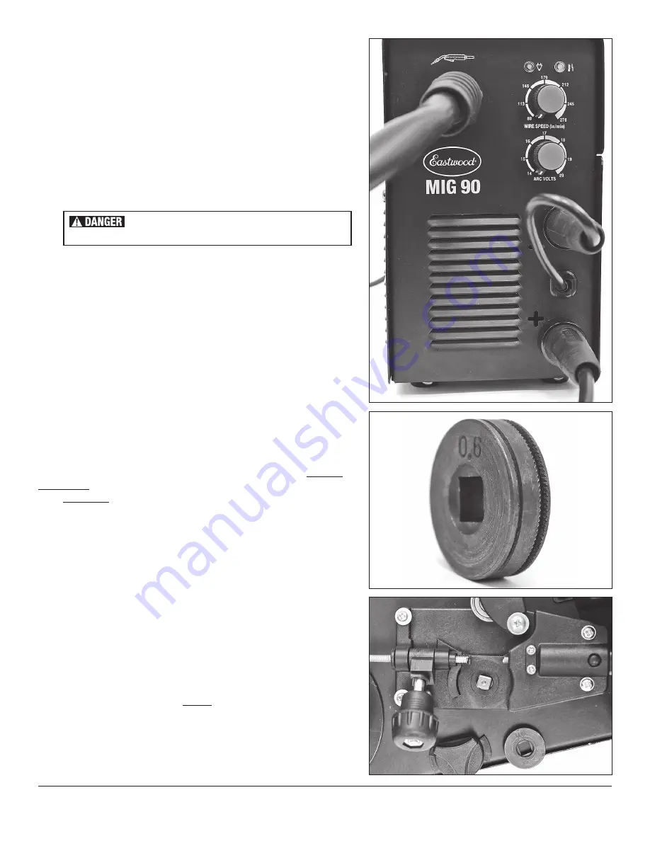
To use a Flux Cored wire, the Polarity of the short Integral Ground Connection Lead
[g]
attached to the Front Panel must be reversed
(Fig 12)
.
• Disconnect the Short, Integral Ground Connection Lead [g] from the Positive (+)
Connection Receptacle
[f]
by rotating the Rubber Insulator 1/2 turn Counter-
Clockwise and pulling outward.
• Align the key of the brass ferrule with the notch of the receptacle at the 12:00
position, then insert the Lead [g] onto the Negative ( - ) Connection Receptacle
[h]
, seat fully and rotate 1/2 turn Clockwise to lock
(FIG 12)
.
• Insert and lock the Ground Clamp Cable into the (+) Positive Connection
Receptacle
[f]
(FIG 12)
.
POSITIONING DRIVE ROLLER FOR WIRE SIZE
The Eastwood MIG 90 Wire Drive Roller has twin grooves to accommodate both
0.023” [0.6mm] and 0.030”/ [0.8mm] wire.
The MIG 90 Drive Roller is factory set and up ready to use 0.023” (0.6mm) solid wire.
IMPORTANT NOTE:
In this position, the narrower, 0.023”/ [0.6mm grove is outboard,
under the wire while the 0.6 marking for the narrower 0.023” [0.6mm] wire is visible
on the outward face of the Drive Roller.
To Clarify; The stamped marking on the side of the drive roller indicates the size of the
groove on the opposite side of the roller
(FIG 13)
.
The groove furthest from the drive motor is the groove that will be used. If setting up
to use larger 0.030” [0.8mm] wire, the “0.8” stamping should be facing the user
when installing it.
Reverse the drive roller position according to the following procedure:
• Open the top door of the Welder to access the drive motor compartment.
• Rotate the Pressure Adjuster out of the way then pivot the Tension Arm away
from the Drive Roller
(FIG 14)
.
• Loosen and remove the Drive Roller Retaining Knob
(FIG 14)
.
• Remove the Drive Roller and view the wire sizes stamped on each side of
the Roller.
• Install the Drive Roller on the square drive, in the proper orientation with the
chosen wire size stamping facing outward
(FIG 13)
.
• Reinstall the Drive Roller Retaining Knob on the shaft.
• Replace the Tension Arm and re-latch the Pressure Adjuster.
ELECTRIC SHOCK CAN CAUSE INJURY OR DEATH!
Disconnect Welder from power supply before beginning.
FIG. 12
FIG. 12
FIG. 13
FIG. 13
FIG. 14
FIG. 14


