Eastwood Elite 64646 Скачать руководство пользователя страница 11

To order parts and supplies: 800.343.9353  >>  eastwood.com 

11

LARGE FRAME ENGLISH WHEEL USAGE

ANVIL SELECTION

•  Each anvil has a different profile intended for creating a variety of contours in metal sheet. Choose the anvil with the profile that most closely matches the 

panel curvature to be achieved.

•  The included Anvil set is comprised of 3” [76mm], 4” [102mm], 5” [127mm], 6” [152mm], 8” [203mm] radiused Anvils 

[K, L, M & N]

•  Illustrated are the included Anvil Radii and the contours they can be expected to product 

(FIG 19)

.

FIG. 19

FIG. 19

PANEL FORMING

English Wheeling is an age-old metal-working skill that many metal workers consider 
an art. Some amazing forms can be created in piece of metal when in the hands of an 
experienced wheeler. Keep in mind that there are differing methods of operation which 
vary among professional wheelers. None are absolutely fixed in stone as the “correct” 
way and none are wrong. It is simply a matter of choosing which method you find most 
comfortable as it is the results that matter most. The best method for learning is to ob-
tain several metal-working books and videos containing material on English Wheeling by 
different well-known metal workers then determine which methods appeal most to you.
The #1 most important rule in becoming an expert in the time-honored art of English 
Wheeling is Practice, Practice, Practice. As with any professional metal working equip-
ment, The English Wheel requires a learning curve to be able to achieve desired results 
that once achieved, prove to be highly satisfying.
The following are several basic elements crucial to English Wheeling:

•  Obtain a stack of 8” x 10”, 20-gauge aluminum and steel panels to use as 

practice pieces.

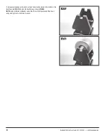
•  Leave a gap equal to the thickness of the workpiece between the Wheel and An-

vil. Place a practice piece of aluminum between them, then raise the Jackscrew 
until the anvil just contacts the metal and the metal contacts the Wheel, allowing 
easy rolling between the Anvil and Wheel 

(FIG 20)

.


  DO NOT overtighten the Jackscrew which would press the 

Anvil against the Wheel! Overtightening will quickly crease and 
harden the metal, create unnecessary effort, and will damage 
the surface of the Anvil. When forming a panel, only minimal 
pressure is required to hold the metal in place. 

FIG. 20

FIG. 20

3” [76mm] 

4” [102mm] 

5” [127mm] 

6” [152mm] 

8” [203mm]

Содержание Elite 64646

Страница 1: ...LARGE FRAME ENGLISH WHEEL ASSEMBLY AND OPERATING INSTRUCTIONS Item 64646...

Страница 2: ...0 343 9353 tech eastwood com CONTENTS 1 English Wheel Assembly A Includes 1 Wheel Yoke Assembly B with 8 203mm Diameter Wheel 1 Anvil Yoke Assembly C with 5 127mm Radius Anvil installed 2 Mounting Bra...

Страница 3: ...rticles can be ejected from the metal surface when rolling Sheet metal edges and corners are sharp and can injure eyes Always wear ANSI approved eye protection when operating this tool Before beginnin...

Страница 4: ...LISH WHEEL COMPONENT IDENTIFICATION FIG 1 FIG 1 FIG 1 Wheel Yoke Tube Mounting Bolts Wheel Yoke Anvil Storage Bracket Type 2 Bracket Type 1 Wheel Yoke Tube Wheel Yoke Tube Mounting Screws Wheel Anvil...

Страница 5: ...helper during assembly is strongly recommended Avoid pinching hands while handling parts and during assem bly The use of thick well fitting work gloves is strongly recommended The wearing of approved...

Страница 6: ...or tool damage it is required to mount the frame securely to the work surface or frame before moving forward 7 16 12mm through bolts or lag screws with washers should be used ELECTRICAL SHOCK HAZARD...

Страница 7: ...ality medium bodied chassis grease to the Jackscrew threads for smoothest operation Thread the Jackscrew into the bottom of the Frame until it begins to engage the bottom of the Anvil Tube FIG 8 Insta...

Страница 8: ...Jackscrew Check alignment of Anvil to the Anvil Tube with the straight edge FIG 11 If necessary loosen the Anvil Yoke set screws and rotate into alignment Verify visually the Wheel Yoke and Wheel are...

Страница 9: ...across the Wheel and the Anvil FIG 15 in both directions FIG 16 The straight edge ideally should lay flush with both Wheel and Anvil faces However a 1 8 3mm gap will not affect wheeling If adjustment...

Страница 10: ...IG 18 If more angle is needed on the Anvil a strip of metal can be placed in the bottom of the Anvil Yoke slot FIG 17 to shim the Anvil Axle up or down FIG 18 NOTE some professional wheelers also util...

Страница 11: ...al metal working books and videos containing material on English Wheeling by different well known metal workers then determine which methods appeal most to you The 1 most important rule in becoming an...

Страница 12: ...htly spaced sweeping W or X pattern over the Anvil for best results Note that the W pattern will produce a curve in one direction only while the X will produce a compound curve or bowl effect Practici...

Страница 13: ...r at both sides The easiest way to accomplish this is Insert the Axle and place one of the spacers over it FIG 27 Carefully as not to knock the spacer off maneuver the Wheel into position and push the...

Страница 14: ...nd Wheel into alignment With the alignment verified the Anvil Tube set screws can be lightly tightened DO NOT over tighten the Anvil Tube Screws as the Anvil Tube needs to able to move up and down smo...

Страница 15: ...To order parts and supplies 800 343 9353 eastwood com 15 NOTES...

Страница 16: ...F version of this manual is available at eastwood com The Eastwood Company 263 Shoemaker Road Pottstown PA 19464 USA 800 343 9353 eastwood com ADDITIONAL ITEMS R D MUST HAVE ACCESSORIES Visit eastwood...

Отзывы: