background image

rev_0.6

81 / 135

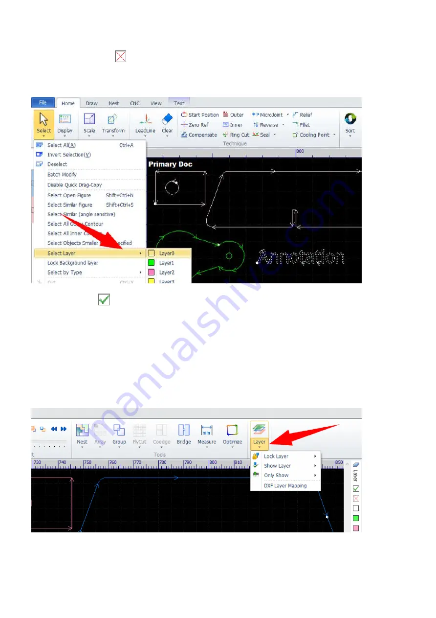
Sometimes, if you want to machine just a part of your design, select those parts that you want to ignore and
then click on the button 

 to tell the software to ignore them while processing. The parts which are assigned

to be not processing are shown in white, but are different with the objects in the background layer. Select the
command Select Layer>Layer0 in Home>Select, only the objects in the background layer will be selected.

Click on the button 

 will restore the parts which are assigned to be not processing temporarily.

There are some layer helper functions to help you manage parts with ease while constructing. Select the
command Select Layer in Home>Select to select all the parts in a specific layer, already mentioned above.
Select the command Lock Layer in the pulldown-menu Home>Layer or in View to lock down the parts in a
layer, helping you select and handle the parts in other layers more easily if they are all crowded tightly
together. Select the command Show Layer or Only Show in the pulldown-menu Home>Layer or in View to
show the parts in a specific group of layers, or show nothing but the parts in the selected layer. This is the
other way to control the part of a design for machining because only the parts shown there will be processed.

Содержание EV-30

Страница 1: ...rev_0 6 1 135 EV 30 Industrial Fiber Laser Cutting System Owner s Manual G U Eagle America Inc www gueagle com 855 S Milliken Ave Ste E Ontario CA 91761 1 626 671 4014...

Страница 2: ...e Control Console For 6kW Only Set up the Control Console For 6kW Only Install the Fiber Laser Connecting the Chiller Connecting the Exhaust s Connecting the Voltage Regulator Connecting the Transform...

Страница 3: ...atically Applied Technologies When Nesting Auxiliary Technologies Check Technology Appendix A For 6kW Only Install the Fiber Laser If any details in this manual is unclear or if you need additional as...

Страница 4: ...wner s manual prior to use You will be ready to use the laser system as soon as you read the first few sections Then you can refer to topics in the remaining sections as you work Notes Used in This Ma...

Страница 5: ...NOT leave a running laser unattended The visible output beam of the Laser Diode Pointer Red Dot Pointer is accessible to the operator While this device employs the same technology as the familiar lase...

Страница 6: ...laser system 2 Get prepared for the installation 3 Unpack the laser system 4 Set up the machine 5 For 3kW only Set up the control console 6 For 6kW only Set up the control console 7 For 6kW only Insta...

Страница 7: ...nside the machine for 3kW lasers a chiller two exhausts only one stronger exhaust for 6kW lasers a voltage regulator a transformer and a set of appropriate assist gas prepared by customers The picture...

Страница 8: ...end that you get your facilities prepared before your laser system shipping That will save a lot of time during the installation especially for the customers who are far from our service agencies 1 Th...

Страница 9: ...volt electrical power The overall power consumption will differ according to the laser configuration of your system Laser Configuration Overall Power Consumption 3 kW 40 kW 6 kW 80 kW NOTE It is recom...

Страница 10: ...ir is used as the assist gas make sure it is WATER FREE AND OIL FREE Otherwise the protective lens in the laser head will get dirty and wet and will be broken by the laser while cutting 5 Operating En...

Страница 11: ...tprint Configuration of the EV 30 Laser System for more details 1 Remove all the protective films and the packing materials on the machine set it in place and set all the accessory packs to the right...

Страница 12: ...rev_0 6 12 135 The control console for 6kW lasers 3 Remove the packing materials on the voltage regulator and set it to the middle of the left side of the machine...

Страница 13: ...ber laser and set it to the back side of the voltage regulator 5 Remove the packing materials on the transformer and set it to the front side of the voltage regulator 6 Remove the packing materials on...

Страница 14: ...rev_0 6 14 135 7 Remove the packing materials on the exhausts only one exhaust for 6kw lasers and set them to the back side of the machine...

Страница 15: ...positioning secure the machine in place by screwing the leveling feet down until they are in firm contact with the ground NOTE Precise leveling of the machine is not necessary but it should be reason...

Страница 16: ...e left side of the machine put the drag chain on it and fix the end of the drag chain Second assemble the X Y intersection part on the left end of the gantry and fix the other end of the drag chain on...

Страница 17: ...ocks to avoid damage during shipment Make sure to remove them before powering on the machine IMPORTANT The machine will DAMAGE itself if the laser head starts moving while the locking blocks are still...

Страница 18: ...k up drawers The machine comes with two pick up drawers which to be placed under the front half and the rear half of the cutting bed After processing parts small enough to fit through the strip cuttin...

Страница 19: ...the cables 2 Put the keyboard mouse and the handheld remote on the console 3 Assemble the alarm indicator Remove the back cover of the panel box assemble the alarm indicator connect the wires and then...

Страница 20: ...nsole cabinet assemble it in place and connect the cables 2 Put the keyboard mouse and the handheld remote on the console 3 Assemble the alarm indicator Assemble the alarm indicator on the top of the...

Страница 21: ...will partner with you to complete the fiber laser installation on your 6kW laser system WARNING ONLY QUALIFIED TECHNICIANS ARE ALLOWED to install the fiber laser Unauthorized installation of the fiber...

Страница 22: ...Chiller 1 Connect the water hoses Connect the low temperature water hoses to the fiber laser pre installed inside the machine for 3kW lasers stand alone for 6kW lasers and connect the high temperatur...

Страница 23: ...MPORTANT Other types of water may corrode the pipeline inside the fiber laser weakening the cooling effects IMPORTANT Add antifreeze to cooling water to protect the fiber laser from freezing if the am...

Страница 24: ...rev_0 6 24 135 Connecting the Exhaust s Connect duct s from the inlet s to the machine and connect duct s from the outlet s to the duct work if there is such a system in your facility...

Страница 25: ...lator 2 For 6kW only Connect the power cord of the fiber laser to a free output of the regulator 3 Connect the power cord of the chiller to a free output of the regulator 4 Connect the power cord of t...

Страница 26: ...e appropriate power cord for the system you ordered IMPORTANT Make sure the transformer is connected to 3 phase 480 volt electrical power standard configuration If a different kind of 3 phase electric...

Страница 27: ...n N2 or compressed air to cut stainless steel aluminum copper and brass and requires oxygen O2 to cut mild steel IMPORTANT If compressed air is used as the assist gas make sure it is WATER FREE AND OI...

Страница 28: ...m 1 Switch on the electrical power 2 Turn on the voltage regulator The exhaust s will be turned on automatically at the same time 3 Turn on the chiller IMPORTANT The fiber laser will NOT work if the w...

Страница 29: ...rev_0 6 29 135 4 For 6kW only Turn on the fiber laser 5 Switch on the assist gas 6 Turn on the main switch Turn on the main switch on 3kW lasers...

Страница 30: ...rev_0 6 30 135 Turn on the main switch on 6kW lasers 7 Release the emergency button Release the emergency button on 3kW lasers Release the emergency button on 6kW lasers...

Страница 31: ...rev_0 6 31 135 8 Turn on the machine Turn on the machine on 3kW lasers Turn on the machine on 6kW lasers 9 For 3kW only Turn on the fiber laser...

Страница 32: ...rev_0 6 32 135 10 Turn on the computer Turn on the computer on 3kW lasers Turn on the computer on 6kW lasers...

Страница 33: ...The laser head will move to its home position the front left corner of the cutting bed make sure there is nothing blocking the way of the laser head and the gantry IMPORTANT Cancel the homing process...

Страница 34: ...Close the CypCut software 2 Turn off the computer 3 For 3kW only Turn off the fiber laser 4 Turn off the machine 5 Turn off the main switch 6 Switch off the assist gas 7 For 6kW only Turn off the fibe...

Страница 35: ...hining process avoid making mistakes or operation delays when switching back and forth between the software and the machine Button Label Function Start To start or resume a job Pause To pause a job Dr...

Страница 36: ...follow the sheet properly Shutter A toggle switch to activate or deactivate the fiber laser s internal main power supply The internal main power supply must be activated before the laser being firing...

Страница 37: ...set in CypCut Step Press the Step button down first then press the jog buttons the Step button can be released then to move the laser head in a fixed distance which is set in CypCut Zero Fn To move t...

Страница 38: ...pCut in this section Workflow 1 Import or construct parts 2 Nest parts 3 Set technology 4 Check technology 5 Machining Import or Construct Parts If you construct your parts with another CAD system e g...

Страница 39: ...Or you can import parts directly into the part library In Nest click on Part and then click on Import Parts You can also construct simple parts directly in CypCut add them to the part library if you w...

Страница 40: ...ill be prepared after setting technology include initial cuts end cuts cooling points micro joints tool correction processing sequence laser power cutting speed etc Check Technology You can simulate m...

Страница 41: ...rev_0 6 41 135 Machining Now you can start machining the parts...

Страница 42: ...a function by selecting the function from a menu by using the mouse or via the keyboard with the Alt key plus the underlined letter in the menu Hot key Click on button Select the function required by...

Страница 43: ...iption White arrow The cursor is on the menu bars the tool bars or the other docking panels I Beam The cursor is on the Draw command window Purple crosshair The cursor is on the drawing window no spec...

Страница 44: ...framed by solid lines and filled with blue the object will be selected only if all its drawing elements fall within the window as shown below Alternately if you click and drag the selection window to...

Страница 45: ...are already selected Select unclosed curve Select the objects which are not closed in geometry Select similar curve Select the objects which are similar with the selected object Select all outer mold...

Страница 46: ...el Function Show Box for unclosed curve To display surrounding boxes around unclosed contours Show unclosed curve as red To display unclosed contours in red Index To display processing sequence Path S...

Страница 47: ...g function to enlarge or minimize the extract Button Label Function Hot Key Adapt to the window Adapt a window of extract to the drawing window Zoom All Adapt all the drawing elements to the drawing w...

Страница 48: ...circles Object snaps can be enabled or disabled through the pulldown menu File User option User parameters In the pop up dialog check the option Auto attach keypoints to enable the functions change th...

Страница 49: ...ou will see the drawing settings which include settings for the object snap functions we just mentioned above Here you can set which elements to display in the drawing window set size of cursor set ba...

Страница 50: ...n menu File Import import parts into the drawing window On the other hand the import functions launched from the menu Nest Part import parts directly into the part library refer to Part Library for mo...

Страница 51: ...rting other files works just like this one Select the command Import from the pulldown menu File then Import DXF File Search for the DXF file in the Windows dialog box and click on Open The placement...

Страница 52: ...User option These settings will be executed on the file when importing i e removing tiny elements deleting duplicated elements etc And then the optimized drawing of the DXF file is displayed in the dr...

Страница 53: ...ons Sometimes there are still open contours shown in red if the view function Show unclosed curve as red is active and other kinds of issues left in the parts after the default optimizations executed...

Страница 54: ...vial To remove drawing elements which are too small Combine near To close opening contours Chop To split scraps into smaller pieces help them fit through the strip cutting bed avoiding interference wi...

Страница 55: ...e part library Unlike importing into the drawing window this function will not display anything in the drawing window and will split drawing elements which are apart from each other into separate part...

Страница 56: ...should follow the steps in Import into the Drawing Window to complete the importing select the contours you want to put in the library and right click to bring up the context menu then select the com...

Страница 57: ...In the same way you should follow the steps in Import into the Drawing Window to complete the importing close the contour manually refer to Drawing Optimizations for more information and then add it...

Страница 58: ...command window or run the function by selecting the function Line in the menu or clicking on the button Line you will see the message below Command New Line please specify start point The PC is waitin...

Страница 59: ...he selected objects and are grouped in the menu Scale in Home Select one or more objects and click on the menu icon to open the dialog Modify Size Set a new size and click on OK to scale the selected...

Страница 60: ...ts by a fixed width i e 100mm or 200mm or to a size times of the current size If you want to scale the objects in the way of dragging and setting select the command Scale and follow the prompts in the...

Страница 61: ...ranslating function The selected objects will be moved in the specified step when the arrow keys on the keyboard are pressed down Or there will be a new copy created at the target location if the Ctrl...

Страница 62: ...he top of the objects to the top most one Bottom Aligned Align the bottom of the objects to the bottom most one Vertically centered Align the center of the objects to the center of the bounding frame...

Страница 63: ...You can find all the drawing functions on the drawing toolbar or in the menu Draw i e Line Rectangle Circle Polyline Text etc If you are familiar with some other CAD systems e g AutoCAD and get used t...

Страница 64: ...xt Draw a letter sequence The command prompts will be shown in the Draw command window no matter how you select the command and you can get hints there on how to complete the command Complete the draw...

Страница 65: ...or entering commands in the Draw command window Select the command OK in the context menu the polyline will be closed automatically if the end point is set to the start point otherwise the segments i...

Страница 66: ...ou confirm the creation You can change text font size and placement of the object in the menu After creation you need to select the command Text to Curve to convert the text object to normal contours...

Страница 67: ...first Select all the parts you plan for nesting in the drawing window right click to bring up the context menu select the menu command Add to Part Lib and then select or input the count of the parts t...

Страница 68: ...in the panel to help you manage the parts and do nesting Icon Command Function Select All Select all parts in the library Select None Select none in the library Invert Selection Invert selection Delet...

Страница 69: ...te all parts from the pulldown menu Part in Nest Sometimes you need to set a special technology on a specific part Double click on the part the software will display it in the drawing window with its...

Страница 70: ...the library the option Selected Parts will be enabled you can check it to do nesting on only the selected parts If there is no sheet in the library only the option Standard plates will be enabled and...

Страница 71: ...the drawing window and select the pulldown menu Set as plate in Nest Plate to make the sheets Technology for nesting are controlled by a group of parameters to set gap between parts set margin on she...

Страница 72: ...e geometry sequence number sheet dimension parts count and utilization rate Click on a result the software will display it in the drawing window with its code showing at the top left corner Click on b...

Страница 73: ...t area to make the result more compact After optimization the result will be tagged with a red label Modified in the summary IMPORTANT Actually you can do all kinds of edits on the nesting result e g...

Страница 74: ...rt on a prepared result select the command Report Information from the context menu and complete sheet unit price and additional information in the pop up dialog Nest Information if you want to get ex...

Страница 75: ...F file At last let s have a recap on the sheets management for nesting There is no material and thickness information included in sheets listing in the tab Plate of the Nest Panel you need to specify...

Страница 76: ...ts etc refer here for more information Right click on a sheet to bring up the context menu you can delete sheets save the sheet to an external file Double click on a sheet the software will display it...

Страница 77: ...nal drawing elements can only be set in the drawing window before the parts are added to the part library Contour Type A part is generally composed of a bunch of closed contours the largest contour fo...

Страница 78: ...s a whole a part The picture on the left shows constructing a part in the drawing window we set lead ins as above All of the two contours count as outer contours The picture on the right shows that th...

Страница 79: ...tion Identify inner outer contour checked at the same time Alternately if you want to set contour types in a reversed way you can select the command Sort in Home with the option The outmost is inner c...

Страница 80: ...layer and are two special layers which can be machined and will be processed at the beginning and at the end of a job and the layer is the background layer which would not be machined but for annotati...

Страница 81: ...ly There are some layer helper functions to help you manage parts with ease while constructing Select the command Select Layer in Home Select to select all the parts in a specific layer already mentio...

Страница 82: ...0 and layer 16 which is the special layer processed in the end They have a same set of layer parameters including general options parameters for cutting piercing and leads First you can give a layer s...

Страница 83: ...g down to the sheet when it moves into the range of the sheet while cutting You can set cutting parameters in the Cut tab Parameter Description Cut speed The nominal cutting speed The actual cutting s...

Страница 84: ...in sheets with high cutting speed the material will catch a lot more power at the start the end and the sharp corners because of the low feeding speed at these positions and result in over burnt edges...

Страница 85: ...feeding time from the piercing height of the current stage to the height of the next stage Pierce height The initial space between the nozzle and the sheet in the current piercing stage Pierce gas The...

Страница 86: ...to the tip of the nozzle Pierce time Time after turning on the laser and before the laser head start feeding down when piercing Extra Blow Time after turning off the laser and before starting the nex...

Страница 87: ...ine Technique Enable the special technology for leading in Cut speed The nominal leading in speed should be lower than the normal cutting speed because a part of laser power is caught by the plasma cl...

Страница 88: ...mal lengths and radius of leads depend on material and thickness Automatic Leads Function Select the contours and then select the command LeadLine in Home In the pop up dialog you can set geometry for...

Страница 89: ...ginal start positions of the contours and the lead ins on the two small circles are longer than their radius not corrected automatically The option Type Angle Length and Radius specify the geometry of...

Страница 90: ...the same And a lead arc is defined with its radius specified in the option Radius and being tangential with both the lead line and the contour at the same time On the other hand for the type Arc the...

Страница 91: ...you want to delete the leads select the contours and then select the command Clear Leadline in Home Clear Sometimes with the option Check leadline checked in the dialog if the software finds somethin...

Страница 92: ...mmand and click on a position out of the contour then click on the contour to set a lead in line there You can only set lead ins with type Line in this way Here we would like to mention a group of fun...

Страница 93: ...change made by the start position function or by setting a lead automatically The seal function is to remove the gaps which are set by the gap function The over function is to set over cuts which may...

Страница 94: ...a specific group of technologies e g 3mm stainless steel cut with a 3kW fiber laser power set to 85 nitrogen used as the assist gas etc 1 Prepare a sample of the material 2 Find the cutting parameter...

Страница 95: ...refer to Contour Type for more information as the option Inner shrink outer expand selected in the dialog There is a library where you can save kerf compensation settings for different materials with...

Страница 96: ...utting paths created by the kerf compensation function click on the button Clear compensation in the dialog or select the command Clear Kerf Compensation in Home Clear when the contours are selected I...

Страница 97: ...when adding the first microjoint And you can add more microjoints on the contours until press the Esc key or select the command Cancel MicroJoint in the context menu Microjoints appear as small gaps...

Страница 98: ...g choose how to set microjoints If you choose By total umber set the number of microjoints in the option Number if you choose By intervals then set the distance between each microjoint in the option I...

Страница 99: ...rev_0 6 99 135 In the example above the software set three microjoints on the contour and change the start position to the microjoint on the right automatically...

Страница 100: ...functions otherwise you can use the fillet function and incorporate the relief function if the part is prepared for bending Cooling Point The cooling point function is to add stops in the cutting pro...

Страница 101: ...cooling points you want to remove And you can select the command Clear Cooling Point in the pulldown menu Home Cooling Point to remove all cooling points Ring Cut The ring cut function adds extra tra...

Страница 102: ...nd select the command Ring Cut again and give it a try with different settings If you want to delete the ring cuts just click on the button Clear path in the dialog Fillet and Relief The fillet functi...

Страница 103: ...135 The relief function adds relieves on corners avoiding warping when bending Select the command Relief in Home Set the radius of relieves in the pop up dialog and then click on the corners you want...

Страница 104: ...software thinks that the contours of a part are logically related and should not be apart All the contours of a group will be selected at the same time only the outmost contour will account for the pr...

Страница 105: ...d Group will be changed to DeGroup Select a group and then select the command DeGroup to break up the group When selecting several groups you can still select the command Group to set up a group of th...

Страница 106: ...rocess more efficient The software will manage to optimize the cutting paths when nesting if the automatic co edge function is enabled in the technology settings Check the option Auto Coedge to enable...

Страница 107: ...rev_0 6 107 135 The co edged contours are set up as groups automatically The small triangles are co edge indicators and are the start positions of the optimized cutting paths...

Страница 108: ...ly First move the parts side by side with overlapped outlines the software will help you on that when the object snap functions are enabled refer to Object Snap Functions for more information Second s...

Страница 109: ...there is no way to restore the original contours but rolling back the operation because they are replaced by the optimized cutting paths The picture below shows the result of applying the command DeGr...

Страница 110: ...commands for the array function i e Rectangular Array Dynamic Array Circular Array and Fill Select the contours and then select the command Array in Home or select the command Rectangular Array in th...

Страница 111: ...menu Home Array Set the spaces between adjacent objects in rows and columns and then click the button OK to start laying out Left click and drag a window in the drawing window and the software will fi...

Страница 112: ...set the angular range for laying out in the option Array range or check the option By Interval and set the angular space between adjacent objects in the option Degree set the number of objects in the...

Страница 113: ...out shown on the right the red circle represents the position of the selected contours in the array which can be set in the option Start angle set the radius in the option Center radius and click the...

Страница 114: ...and then select the command Fill in the pulldown menu Home Array In the pop up dialog set the size and the margin of the plate set the gap between adjacent parts and click the button OK to complete t...

Страница 115: ...w parts for machining directly The most simple way to preview the processing sequence is to let the software show it around the parts Select the command Index in the pulldown menu Home View then you w...

Страница 116: ...are many objects e g in a nesting result In addition you can use the simulation function to preview the processing sequence refer to Check Technology for more information CypCut has a set of strategie...

Страница 117: ...eration Button Function Move the object one step to the back Move the object one step to the front Move the object to the last Move the object to the first You can also select the command to sort the...

Страница 118: ...em connecting with each other This function is often used in two situations First to collect several parts together after cutting In this case you make the parts which are related with each other and...

Страница 119: ...ss the Esc key or select the command Cancel Bridge Joint in the context menu to cancel the command Second to keep the inner pieces from being apart on openworks For example when cutting out some openw...

Страница 120: ...ting process when cutting an array of rectangles or circles Select the array of rectangles and then select the command FlyCut in Home or select the command Linear FlyCut in the pulldown menu Home FlyC...

Страница 121: ...e broken up and re arranged all the horizontal outlines will be cut in order in a linear way same to all the vertical outlines You can use the simulation function to check it out and get more sense ab...

Страница 122: ...t the command Circle FlyCut in the pulldown menu Home FlyCut Set parameters in the pop up dialog and click the button OK to complete the operation The start positions and the directions of the cutting...

Страница 123: ...the machining panel or select the command Simulate in the menu CNC the software will start simulating In the section Simulate in CNC you can drag the slider or click the button Speed Up or Speed Down...

Страница 124: ...d you can get a brief summary about the machining progress when simulating in the system information window Finally if you want to stop simulating just press the Esc key or click the button Stop in th...

Страница 125: ...rev_0 6 125 135 Appendix A For 6kW Only Install the Fiber Laser 1 Prepare the machine to set the fiber 1 Open the access panel of the laser head 2 Remove the covers of the Z axis drag chain...

Страница 126: ...rev_0 6 126 135 3 Remove the access panel on top of the Z axis...

Страница 127: ...rev_0 6 127 135 4 Remove the covers of the X axis drag chain...

Страница 128: ...rev_0 6 128 135 5 Remove the access panel at the end of the X axis drag chain 6 Remove the side access panel of the X Y intersection...

Страница 129: ...rev_0 6 129 135 7 Remove the corner access panel of the X Y intersection...

Страница 130: ...rev_0 6 130 135 8 Remove the covers of the Y axis drag chain 9 Remove the access panel at the end of the Y axis drag chain...

Страница 131: ...rev_0 6 131 135 2 Set the fiber through to the laser head Set the fiber through the Y axis drag chain the X axis drag chain and the Z axis drag chain to the laser head...

Страница 132: ...tant to prevent it from tangling with other cables and hoses in the drag chains 3 Connect the fiber to the laser head 1 Remove the connections on the laser head Remove the green signal line on the lef...

Страница 133: ...rev_0 6 133 135 2 Remove the laser head from the Z axis slider...

Страница 134: ...laser head Remove the protective cap from the end connector of the fiber Remove the protective cap from the QBH interface of the laser head Hold the laser head in horizontal aim and set the connector...

Страница 135: ...g into the laser head and the upper protective lens might get dirty and would be broken by the laser while cutting 4 Set the laser head back onto the Z axis slider 5 Set the connections back on the la...

Отзывы: