background image

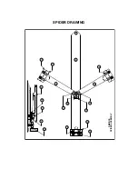
DRAWING KEY

ITEM DESCRIPTION

P/N

1

Locknut

612541

2

Adjusting bolt, ss

400177

3

Pin, spring (split), ss, type 420

640136

4

Chain, sash, ss, 1/0

100356

5

Chain clip

400182

6

Enclosure, FG 5x5x3

630604

7

Bracket, cell, PVC-1

400244

8

Load cell, 40#, 14”, 350 ohm

500317

9

Term. block, 6 ckt, screw term.

532061

10


Lid, enclosure, FG

Part of Item 6 above

11


Not used

---------

12


Screw, 10B x 5/8 Self tap, ss

611060

13


Pivot screw

400229

14


Disc

400178

15


Deck

400178

16-35


Not used

----------

36

Disc washer

400154

37

Perimeter flexure

400143

38

Perimeter clamp

400144

39

Center clamp

400145

40

Center flexure

400142

41

Short lever

400160

42

Long lever

400141

43

Screw, 6A-3/8, self tap hex

610684

44

Screw, 10-24 x 3/8 Hex head

611061

45

Screw, 10B-5/8 Self tap Phillips

611060

46

Screw, 10A-3/8 Self tap hex

611028

47

Bolt, 10-32 x 3 1/4

611013

Содержание DCS302

Страница 1: ...DCS302 DUAL CYLINDER SCALE INSTALLATION OPERATION MANUAL Eagle Microsystems Inc 366 Circle of Progress Pottstown PA 19464 www eaglemicrosystems com phone 610 323 2250 fax 610 323 0114...

Страница 2: ...ndependently and displays the net weight on separate digital indicators Wall mounting bracket and safety chains are optionally available These can adapt to different cylinder sizes All scales are fact...

Страница 3: ...lay Instrument to a suitable and convenient wall surface Remove instrument cover and mount instrument to the wall with 10 screws or suitably sized masonry or hollow wall anchors as applicable The inst...

Страница 4: ...SCALE INSTALLATION 16 30 DCS302 FOOT PRINT 2 1 2 15FT 6 CONDUCTOR CABLE WALL MINIMUM WALL CLEARANCE C L 1 5 8 RECOMMENDED ELEVATION 40 5 5 8 CHLORINE 30 1 2 CLR HOLE 4 PLCS 31 1 2 16 18 30...

Страница 5: ...EI2000 INDICATOR Wall Mounting Dimensions Enclosure conforms to NEMA 4X 7 5 8 5 3 8 ctr to ctr mounting holes 5 5 8 ctr to ctr mounting holes 6 5 8 3 3 16 EI 2000...

Страница 6: ...TE BLACK YELLOW Load Cell Connector Mating Half P4 A B C R T IN RS485 RS232 Com Mating Half P6 Analog 4 20 mA Output P3 RIGHT POS LEFT POS LEFT NEG RIGHT NEG CONNECTOR PLUGS EI2000 TRANSMITTER 15 CABL...

Страница 7: ...Down arrow keys Once the Gross Weight display is set to the known 250 lbs the SEL PB is pressed and the display will change to Weight Remaining and show 150 lbs The weights are removed Readout should...

Страница 8: ...DCS302 DUAL CYLINDER SCALE BASE SPIDER DRAWING 12 15 14 13 48 49 Not Shown 10 1 4 5 2 3 6 7 8 9...

Страница 9: ...SPIDER DRAWING DMS DCS SPIDER ASSEMBLY BASE DISK 36 37 13 41 38 37 39 41 41 42 37 40 38 45 46 44 43 44...

Страница 10: ...closure FG Part of Item 6 above 11 Not used 12 Screw 10B x 5 8 Self tap ss 611060 13 Pivot screw 400229 14 Disc 400178 15 Deck 400178 16 35 Not used 36 Disc washer 400154 37 Perimeter flexure 400143 3...

Страница 11: ...be replaced from the terminal block Loosen the strain relief on the bottom of the divider plate and pull the wire through Load cells and adjustment bolt pictured below for reference Note how high the...

Страница 12: ...o make sure the chain is not twisted Straighten it if needed or the weight readings will not track properly as gas is drained from the cylinder Recalibrate the side with the new load cell This can be...

Отзывы: