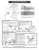
Step 1 - Cut out holes.
• Cut out and form flanged openings in countertop to fit
inside of warmer. Also, cut hole for the control panel.
• Be sure to hold to all minimum dimensions shown.
flanges
formed in
opening
Step 3 - Install unit.
• Install from underside of countertop with
control toward front.
• Attach unit to countertop with screws or
rivets (not supplied).
• Wipe off excess silicone with clean cloth
before it cures.
countertop
countertop
screw or
rivet (not
included)
unit
unit
(end view)
INSTALLATION INSTRUCTIONS
2
Step 2 - Apply silicone rubber.
Apply bead of silicone rubber to underside of
flanges formed in opening.
(Note: Silicone can be purchased at a local
hardware store.)
flanges formed
in opening
flange formed
in opening
silicone
countertop
countertop
2
3
⁄
4
˝ x 5
1
⁄
8
˝
cutout
control
knob
mounting
screws (2)
screws or
rivets not
included
(4)
recessed
control panel
Step 4 - Attach controls.
• Remove control from recessed
control panel by removing knob
and two mounting screws.
• With indicator light still attached
to panel, insert recessed control
panel through 2
3
⁄
4
˝ x 5
1
⁄
8
˝ cutout
from rear of enclosure.
• Remount control to recessed
control panel and attach knob.
• Recessed control panel should
be mounted to enclosure using
screws or rivets (not supplied).
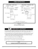
(For wiring instructions, see page 3.)
Parts List
Replacement parts may be purchased through our
local Authorized Parts & Service Center.
#
qty
description
#1
6
pop rivet
#2
1
heater (1200W 120V; 1200W 240V;
1600W 240V; or 1600W 277V)
#3
1
hi limit (for infinite control units)
#4
1
120V or 240V infinite control
(for infinite control units),
or thermostatic control
(for thermostatic control units)
#5
1
knob
#6
3
heat element support bracket
#7
1
heat cover assembly
#8
1
indicator light
#9
1
bowl
#10
1
recessed control panel


