background image

26

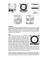
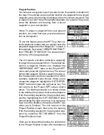
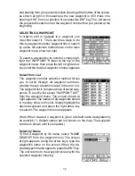
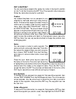
plot trail in a specific memory location, choose “SAVE TRAIL” from the
“TRAIL OPTIONS” menu.  A new screen appears. Highlight the desired
number that you wish to save the current trail under, (i.e. “Trail 1 or Trail 2)
and press the right arrow key. Your current trail is saved. Press the EXIT
key to erase this menu.

Update Options
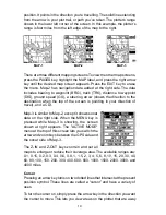
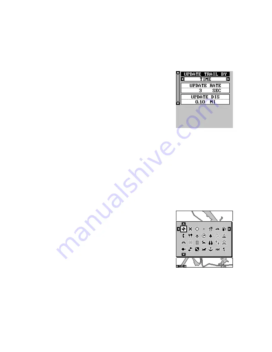
By default, the plotter places a dot on the screen
every 3 seconds to create the plot trail. You can
change this time from once per second to once
every thirty minutes. The plot trail can also be
updated by distance instead of by time. The dis-
tance update rate can be set from 0.01 to once
every 10 miles.

From the trail options menu, choose “UPDATE
OPTIONS”.  Select “UPDATE TRAIL BY” to change the update from time
to distance. To change the rate or distance, simply select either the “UP-
DATE RATE” or ‘UPDATE DIS” menus as appropriate, use the left or right
arrow keys to adjust it, then press the EXIT key to erase the menu.

ICONS
The plotter has 28 symbols or “icons” available that can be placed any-
where on the screen. They can be used to mark fishing or hunting loca-
tions, landmarks, boat ramps, and virtually any point of interest. An icon
can be placed at your present position or at the cursor’s location.

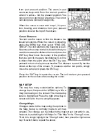
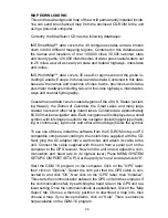
To place an icon at your present position, simply
press the ENT key while the mapping screen is
on. The screen shown at right appears. Use the
arrow keys to highlight the desired icon. Now
press the ENT key again. The mapping screen
reappears with the icon showing at the position
you were at when the ENT key was pressed. On
the screens shown at the top of the next page,
the shipwreck icon was placed.

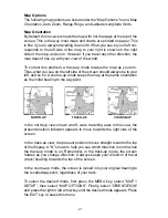
To place an icon at the cursor’s position, first use the arrow keys to move
the cursor to the location that you wish to place the icon. Next, press the
ENT key. Now select the icon using the arrow keys. While it’s selected,
press the ENT key. The map reappears with the icon placed at the cursor
crosshairs. Press the EXIT key to erase the cursor.

Содержание AccuMap

Страница 1: ...INSTALLATION AND OPERATION INSTRUCTIONS AccuMap and UltraMap TM TM ...

Страница 2: ...on tools when trav elling to a waypoint but will also visually check to make certain a clear safe path to the waypoint is always available The operating and storage temperature for your unit is from 4 degrees to 167 degrees Fahrenheit 20 to 75 degrees Celsius Extended storage temperatures higher or lower than specified will cause the liquid crystal display to fail Neither this type of failure nor ...

Страница 3: ... can radiate radio frequency energy and if not installed and used in accor dance with the instructions may cause harmful interference to radio com munications However there is no guarantee that interference will not oc cur in a particular installation If this equipment does cause harmful inter ference to radio or television reception which can be determined by turn ing the equipment off and on the...

Страница 4: ...tions 3 AccuMap 3 UltraMap 4 Antenna 5 Transducer 6 INTRODUCTION TO GPS 10 OPERATION 12 Satellite Status Screen 13 FindingYour Position 14 Auto Search 14 Manual Initialization 14 Position Acquisition 15 Modes 15 Navigation Screens 15 Course Deviation Indicator CDI 18 Map 18 Cursor 19 Map Setup 20 Change Maps 20 Map Options 21 Map Orientation 21 Range Rings Grid Lines 22 Autozoom 22 Map Details 23 ...

Страница 5: ... Signal Processing 62 Range Automatic 62 Manual 63 Chart Options 63 Chart Speed 63 Chart Stop 63 Zoom 64 Fish ID 65 FISHTRACK 65 Chart Display 66 Zoom Bar 66 Zone Bar 67 Chart Cursor 67 Digital Sonar 67 Alarms 68 Depth Alarms 68 Zone Alarm 69 Fish Alarm 69 Keel Offset 69 Calibrate Speed 70 SONAR TROUBLESHOOTING 71 UPS Return Service 74 Warranty 76 Datum List 77 Table of Contents ...

Страница 6: ...Notes ...

Страница 7: ...e troubleshooting section in the back of this manual You may find the solution to your problem there The Eagle customer service department also has representatives available to answer your questions on our toll free telephone lines See the back page of this manual for more information We want your experience with our equipment to be a happy one Good luck and good fishing INSTALLATION Mounting All ...

Страница 8: ...e positive lead black is negative or ground Make certain to attach the in line fuse holder to the red lead as close to the power source as possible For example if you have to extend the power cable to the battery or power buss attach one end of the fuse holder directly to the battery or power buss This will protect both the unit and the power cable in the event of a short Use a 3 amp fuse IMPORTAN...

Страница 9: ... radiate noise when transmitting so be certain to keep the sonar s wires away from it You may need to route the sonar unit s power cable directly to the battery to isolate it from other wiring on the boat CABLE CONNECTIONS AccuMap Only RED 12 VDC BLACK GROUND GREEN NMEA RECEIVE ANTENNA WHITE NMEA TRANSMIT EAGLE ...

Страница 10: ...SPEED TEMP SENSOR OPTIONAL WHITE NMEA TRANSMIT EAGLE BLACK GROUND TO 12 VDC See Note 1 Notes 1 If the NMEA wires are not used then the NMEA adapter cable is not required The speed temperature sensor s cable can be attached directly to the UltraMap NMEA ADAPTER CABLE POWER TRANSDUCER CABLE ...

Страница 11: ...ng a satellite Do not mount it in front of radar antennas They radiate high energy that can interfere with the GPS signal Once you ve determined the mounting location use the template on page 51 in this manual to drill the holes for the screws The screws supplied with this antenna are 4mm x 30mm about 1 1 8 long Drill 4 75 mm 3 16 holes for the mounting screws If you route the cable through the mo...

Страница 12: ...pole where it can be easily routed down the pole to the GPS receiver The threads on the pole mount adapter accept a standard marine antenna mount MAGNET SPEED TEMPERATURE SENSOR UltraMap Only If you re installing a temperature or speed temperature sensor read the sensor s mounting instructions before making the installation Route the sensor s cable directly to the UltraMap and plug it into the con...

Страница 13: ... GOOD LOCATION GOOD LOCATION GOOD LOCATION GOOD LOCATION GOOD LOCATION POOR LOCATION POOR LOCATION POOR LOCATION POOR LOCATION POOR LOCATION 4 If possible route the transducer cable away from other wiring on the boat Electrical interference fromVHF radio engine wiring bilge pumps and areators can be displayed on the sonar s screen Use caution when routing the transducer cable around these wires CA...

Страница 14: ...gree angle DOT 2 Slide the transducer between the two ratchets Temporally slide the bolt though the transducer assembly and hold it against the transom Look ing at the transducer from the side check to see if it will adjust so that its face is parallel to the ground If it does then the A position is cor rect for your hull If the transducer s face isn t parallel with the ground remove the transduce...

Страница 15: ...of the slots for the mounting holes Drill two 5 32 holes in the marked locations for the 10 screws supplied with the transducer NUT METAL WASHER RUBBER WASHERS METAL WASHER BOLT TRANSOM SIDE VIEW 5 Attach the transducer to the transom Slide the transducer up or down until it s aligned properly on the transom as shown above Tighten the bracket s mounting screws Adjust the transducer so that it s pa...

Страница 16: ...or may even prevent operation INTRODUCTION TO GPS The Global Positioning System GPS was developed by the United States Department of Defense as a 24 hour a day 365 days a year global navi gation system for the military Civilian availability was added but with less accuracy using the same satellites Twenty four satellites orbit the Earth Three of these satellites are spares unused until needed The ...

Страница 17: ...ter performance and who doesn t many manufacturers including Eagle sell a DGPS receiver that attaches to your GPS receiver The DGPS system transmits correction signals that nullify the effects of SA The DGPS receiver takes signals from these land based transmitters and gives them to the GPS receiver which then uses them to show a more accurate position The ironic part is the federal government imp...

Страница 18: ...ng it once while the unit is operating turns on the screen s back light To prevent an accidental shutdown you must hold the PWR key down for a few seconds to turn the unit off PWR ENT MENU EXIT PAGES WPT ZOUT ZIN Most of the unit s features are found on menus You can view the menus by pressing the MENU key This product has Intelligent Menus There are many menus that pertain to only the sonar for e...

Страница 19: ...raph are the bar graphs one for each satellite in view Since the unit has twelve channels it can dedicate one channel per visible satellite Therefore if only six satellites are visible only six bar charts show at the bottom of the screen The wider the bar on the graph the better the unit is receiving the signals from the satellite The number in the upper left corner is the expected horizontal posi...

Страница 20: ... you turn the unit on until it locks onto the satellites and shows a position Once the unit locks onto the satellites it should take less than a minute to find your position the next time it s turned on provided you haven t moved more than approximately 100 miles from the last location it was used Manual Initialization If you don t want to wait for the Auto Search then you may be able to speed up ...

Страница 21: ...ion Acquired message and all other data is not flashing The unit must be locked onto at least four satellites to determine altitude It only takes three satellites to determine position You can navigate with this unit if the alti tude is flashing simply ignore the altitude display until it quits flashing REMEMBER DO NOT NAVIGATE WITH THIS UNIT UNTIL THE NUM BERS STOP FLASHING MODES The UltraMap has...

Страница 22: ...the one at right when you re not navi gating to a waypoint Your position is shown by an arrow in the center of the screen Your trail history or path you ve taken is depicted by the line extending from the arrow The arrow pointing down at the top of the compass rose indicates the current track direction of travel you are taking This is also shown in the TRK track box in the upper right corner of th...

Страница 23: ... a vertical dotted line The default for the cross track error range is 0 20 mile For example if the present position symbol touches the right cross track error line then you are 25 mile to the right of the desired course You need to steer left to return to the desired course You can use the ZIN or ZOUT keys to change the cross track er ror range A circle depicting your destination way point appear...

Страница 24: ...f the solid line is on either of the dotted lines then you are 0 20 mile off course Remember if the line moves to the left then you are too far to the right of the desired course line and vice versa Using the CDI with a mapping screen helps you visualize your position in relation to the course The screen on the right shows that we are off course to the right The vertical bar has moved to the left ...

Страница 25: ...tion when the top of the screen is pointing in your direction of travel and a CDI Map 3 is similar to Map 2 except it shows sonar data on the right side When the MENU key is pressed while Map 3 is showing the screen shown at right appears The ACTIVE MODE menu at the top of this screen lets you switch the arrow and zoom keys between the GPS side and the sonar side of Map 3 The Z IN and Z OUT keys z...

Страница 26: ...o A line is drawn from the point when the ENT key was pressed to the cursor s present location The distance covered by the line shows at the top of the screen To measure another two points simply move the cursor and press the ENT key Press the EXIT key to erase the cursor The unit centers your present position on the screen after erasing the cursor MAP SETUP The map has many customization options ...

Страница 27: ... up mode keeps the map at the same orientation as the initial bearing to the waypoint NORTH UP TRACK UP COURSE UP In the north up view shown at left we re travelling east In this view the present position indicator appears to move towards the right side of the screen In the track up view the present position moves straight towards the top of the display A N shows to help you see which direction is...

Страница 28: ...mpetitive units force you to make It works in conjunction with the navigation features First recall a waypoint See the waypoint section for more information on navigating to a waypoint Then with the autozoom mode on the unit zooms out until the entire course shows from the present position to the destination waypoint recalled waypoint As you travel towards the destination the unit automatically be...

Страница 29: ...mes on the map such as Lake Tahoe or Mississippi River off or on The default is on Press the left arrow key to turn them off Map Detail The detail shown on the background map diminishes as the screen is zoomed out This prevents cluttering of the display or overlapping of text and graphics which can make it unreadable There are two detail levels normal and high The difference between the two shows ...

Страница 30: ...ackground map This line depicts the detailled map bound aries To turn this off select Map Bounds from the map details menu then press the left arrow key Map Symbols When the nav aid data is downloaded to this unit buoys and other naviga tional aids can be turned off or on by using Map Symbols on the Map Details menu To find this menu press the down arrow key while on the Map Details menu until Map...

Страница 31: ...e screen select Clear Trail from the Trail Options menu A message appears ask ing if you really want to erase the plot trail Follow the instructions on the screen When the trail is erased the unit returns to the map screen FlashTrail By default the plot trail flashes once per second This typically makes it easier to see the plot trail against the background map To turn the flash ing off select FLA...

Страница 32: ...ys to adjust it then press the EXIT key to erase the menu ICONS The plotter has 28 symbols or icons available that can be placed any where on the screen They can be used to mark fishing or hunting loca tions landmarks boat ramps and virtually any point of interest An icon can be placed at your present position or at the cursor s location To place an icon at your present position simply press the E...

Страница 33: ...f you want to erase all icons that have been placed on all map screens To erase only a certain type of icon select the DELETE ICON TYPE menu The icon menu appears Highlight the icon style that you want to erase from memory then press the ENT key The unit returns to the map screen with only the selected icons erased You can delete individual icons by selecting DE LETE FROM MAP Once this menu is sel...

Страница 34: ...e approximately 60 000 marine navigation aids Each navigation aid is displayed as a small symbol with information useful to the navigator including light type flash ing or continuous light color and other aid markings below the symbol To use one of these install the software from the CD ROM onto your PC compatible computer according to the insturctions supplied with the CD Next plug the AC adapter...

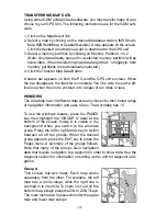
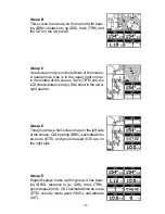
Страница 35: ...s zoomed in to ranges of ten miles or less WINDOWS The UltraMap has 13 different data screens chosen for their broad range of navigation information and ease of use The AccuMap has 10 To use the windows feature press the PAGES key then highlight the GROUP A label at the bottom of the screen Group A is visible in the background when you switch to the windows group Press the left or right arrow key ...

Страница 36: ...e middle of the screen Track TRK and the CDI shows distance to go DIS show in the lower right quarter Group D This group has a half screen map on the left side of the screen CDI bearing BRG estimated time en route ETE and ground speed GS are on the right side Group E Digital displays make up this group It has bear ing BRG distance to go DIS track TRK ground speed GS CDI estimated time en route ETE...

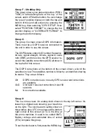
Страница 37: ...PS receiver re ceived the satellite corrections AGE all show in the top half of this screen The DGPS corrections at the bottom of the screen shows a list of the satellites in view The satellite s number is follow by an identifier showing its status They are as follows OK DGPS corrections are in use by GPS receiver and corrections are available OLD Unit hasn t received corrections in last 60 second...

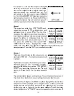
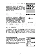
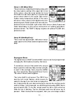
Страница 38: ...nu Highlight the TRIP START GS label then press the left or right arrow keys until the desired speed appears Press the EXIT key to erase this screen Group J There are three timers on this screen and an odometer TRIP DIS The trip timer is described in group I Trip distance measures the distance you ve trav elled since it was last reset To reset the trip meter press the MENU key then select TRIP MET...

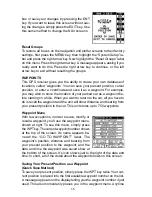
Страница 39: ...a bel Press the right arrow key Press the EXIT key to erase the menu The time you set shows in the UP TIMER box The timer continues counting until you stop it When it reaches the alarm s time setting a tone sounds Press the EXIT key to shut the alarm off The countdown timer starts from a time that you enter and counts down to zero Note When the countdown timer reaches zero it begins count ing up u...

Страница 40: ...s can be reprogrammed changing the informations shown by the boxes To customize a screen first switch to the screen that you want to customize Map 2 shown at right is used in this example Next press the MENU key then select the Reprogram Boxes menu The screen shown below appears This is the MAP 2 edit screen The BRG box near the left corner flashes which means it s ready for change If you don t wa...

Страница 41: ...n a hike When you want to return to the car all you have to do is recall the waypoint and the unit will show distance and bearing from your present position to the car This unit stores up to 750 waypoints Waypoint Menu With few exceptions in order to save modify or recall a waypoint you ll use the waypoint menu shown at right To see this menu simply press theWPT key The current waypoint number sho...

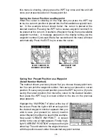
Страница 42: ...OCATION PRESS WPT KEY TWICE SavingYour Present Position as a Waypoint Select Number Method The method shown previously doesn t let you choose the waypoint num ber You can pick the waypoint number then save your present or cursor position To save your present position press the WPT key once If you re saving the cursor position first move the cursor to the desired location then press the WPT key A s...

Страница 43: ...tel lites being tracked and their location relative to your position and so on However even with SA turned on this GPS receiver can show surpris ingly accurate position information If you wish to increase the accuracy of a saved position use the waypoint averaging method This method requires the unit to remain untouched at the location that you want to save preferably for at least one hour Longer ...

Страница 44: ...ew waypoint from The default ref erence is waypoint number one Highlight the REFERENCE WPT label on the Project WPT menu and press the right arrow key The screen below right appears Select a waypoint using ei ther the waypoint number or waypoint list In this example waypoint 4 was chosen When you ve chosen the waypoint highlight the SET REFER ENCE label and press the right arrow key The unit retur...

Страница 45: ...m List The waypoint number selection method forces you to scroll through all waypoint numbers whether there s a location saved in them or not The waypoint list is composed only of saved way points To use the list select WAYPOINT LIST from the waypoint menu The screen shown at right appears The names of all waypoints stored in memory show on this list Simply highlight the desired waypoint and press...

Страница 46: ...oint The name can have up to eight characters To do this first select the waypoint that you wish to name then choose EDIT NAME from the Edit Way point menu A screen similar to the one at right appears Press the up or down arrow keys to select the first letter in the name Press the right arrow key to highlight the next position in the name Repeat this sequence until you ve entered all of the letter...

Страница 47: ...The From label is highlighted at the top of the screen Press the right arrow key until the waypoint number that you want to move appears In this example we selected waypoint number 1 Now press the down arrow key once to highlight the To label Press the left or right arrow key until the number that you want to move the waypoint to appears Again in this example we chose to move waypoint number 1 to ...

Страница 48: ...Switching to the MAP 1 screen shown at right shows the starting location S the recalled waypoint 4 the plot trail from the starting location to the present position and the present position The present position arrow also shows the direction of travel track Navigating to a Cursor Position This unit lets you navigate to a location without storing it in the waypoint database by using the map and cur...

Страница 49: ...ION This unit continues to navigate to a recalled waypoint the last waypoint in a route or the cursor position until you stop it To stop the navigation function press the MENU key then press the up or down arrow keys until the Cancel Nav label is highlighted Press the right arrow key The unit stops showing navigation information ROUTES You can connect several user waypoints together to form a rout...

Страница 50: ...ht the ADD TO ROUTE label and press the right arrow key The unit returns to the route screen with the first waypoint at the top of the list High light the next waypoint location beneath the first waypoint and press the right arrow key Now re peat the previous steps to select the second way point for your route After selecting the second waypoint the unit returns to the waypoint list screen The sec...

Страница 51: ...oesn t delete the waypoint from the database it simply removes it from the route Waypoint Statistics By default this unit shows the distance and bearing from each waypoint in the route to the next It will also show estimated time en route ETE estimated time of arrival ETA or the waypoint names NAMES To view the different statistics highlight the SHOW INFO DIS BRG label then press the left or right...

Страница 52: ... arrival alarm the unit automatically switches to the next waypoint on the list showing navigation data to that waypoint and so on until the last way point on the route list has been reached Note The arrival alarm does not have to be turned on The unit continues to show navigation data to the last waypoint in the route until you end the navigation See Cancel Navi gation Following a Route Auto Star...

Страница 53: ... appears asking if you really want to erase the route If you press the right arrow key the route will be erased If you select Yes by pressing the right arrow key the unit then asks if you want to erase the waypoints used in the route from memory also Press the right arrow key again to erase them or the left arrow key to leave the waypoints in memory The unit returns to the routes menu Press the EX...

Страница 54: ...ay has lights that can be turned on for night use To turn the lights on simply press the PWR key To turn them off press the PWR key again A light bulb indicator on the satellite status screen shows when the lights are on The default light level is maximum To reduce the level select BACK LIGHT LEVEL then press the left arrow key until the lights are at the desired level To increase the light level ...

Страница 55: ...ow key You can change any or all of the settings on this page When you re fin ished press the EXIT key NMEA DGPS This product transmits data through the power data port in the back of the unit using NMEA 0183 format version 1 5 or 2 0 The data is used by other electronic devices such as marine autopilots for position and steer ing information DGPS on the other hand is a data input DGPS is an acron...

Страница 56: ...fferent sentence The default setting for these sentences is on In other words it automatically sends these sentences when NMEA is turned on To turn any of these off move the black box to the desired menu and press the left arrow key Press the EXIT key when everything on this screen is the way you want it DGPS This unit will recognize Starlink and Magnavox automatic DGPS receiv ers If you have eith...

Страница 57: ... DGPS receiver s manual for the proper data settings Highlight the menu item you need to change Press the left or right arrow keys to change them The serial port defaults are 4800 baud no parity and 8 data bits Press the EXIT key to erase this menu Reset Groups To return all window groups and boxes on the navigation and mapping screens to their factory defaults select Reset Groups on the System Se...

Страница 58: ...0 zones each 6 degrees wide in longitude German Taiwan British Irish Swedish Swiss New Zealand and Finn ish grid systems are the national coordinate system used only in their respective countries In order to use these grid systems you must be in the respective country This unit will pick the matching datum for you when you select the grid See the Datums section for more information The military gr...

Страница 59: ... highlight the GPS Setup label and press the right arrow key Now highlight the Select Da tum label Finally press the right arrow key again A screen similar to the one at right appears The WGS 84 label is highlighted To change it simply press the up or down arrow keys to high light the desired datum then press the ENT key This selects the datum and erases the select datum menu A list of the datums ...

Страница 60: ... Select Map Fix from the list and press the EXIT key All posi tion information now shows as a distance from the reference point you entered and saved as a waypoint earlier Set PCF Offset Another method used to make your display match a chart or map is called PCF or Position Correction Factor This unit gives you the capability to move or offset the position shown on the display to match one on the ...

Страница 61: ...t In this example we entered 0 degrees 0 047 minutes north latitude and 0 degrees 0 244 minutes east longitude That is the difference between the present posi tion shown by this unit and the one on our chart After you ve entered the latitude longitude correction press the ENT key to accept it The PCF entry screen is erased and the unit returns to the navigation or mapping screens with the correcti...

Страница 62: ...message if you drift 1 of a mile or more to the right or left of the line to the waypoint The anchor alarm is triggered when you drift outside of a preset radius Again using the 1 mile as an example if you re an chored and your boat moves more than 1 of a mile the alarm will flash a message and sound a tone To use any of these alarms first press the MENU key then select the ALARMS menu Next se lec...

Страница 63: ... in the world To use it press the MENU key then highlight SUN MOON CALC and press the right arrow key The screen shown at right appears Both calculators work identically The sunrise sunset calculator is used for this example The sun and moon data for today s date appear in the center of the screen A moon symbol shows in the moonrise moonset box showing the ap proximate phase of the moon The arrow ...

Страница 64: ...position for the simulator is your present position If you want to change the starting position highlight the SET START WPT label on the Simulator Setup menu then press the right arrow key You can select any waypoint as the simulator s starting point Select the starting point by pressing the right arrow key on the WPT label until the desired starting waypoint number appears Now highlight the SET S...

Страница 65: ...bottom depth shows at the top left corner of the screen The word AUTO at the screen s top center shows that it s in the automatic mode freeing you from sensitivity range and noise rejec tion adjustments Split Chart A split chart shows the underwater world from the surface to the bottom on the right side of the screen The left side shows an enlarged version of the right side The zoom range shows at...

Страница 66: ...ensitivity level shows a good solid bottom signal with Grayline and some surface clutter The sensitivity is adjusted to keep a solid bottom signal displayed plus a little more when the unit is in the automatic mode This gives it the capa bility to show fish and other detail However situations occur where it becomes necessary to increase or decrease the sensitivity This typically happens when you w...

Страница 67: ...This helps distinguish weeds from trees on the bottom or fish from structure GRAYLINE is adjustable Since GRAYLINE shows the difference between strong and weak signals adjusting the sensitivity may require a different GRAYLINE level also The level chosen by the unit at power on is usually adequate for most conditions Experiment with your unit to find the GRAYLINE setting that s best for you To adj...

Страница 68: ...mechanical sources such as bilge pumps engine ignition systems and wiring air bubbles passing over the face of the transducer even vibration from the engine In all cases noise can produce unwanted marks on the display The ASP feature has two levels Normal and High If you have high noise levels try using the High ASP setting However if you are having trouble with noise we suggest that you take step...

Страница 69: ... to select a different range Press the left or right arrow keys to decrease or increase the range The available ranges are 0 10 20 30 40 60 100 150 200 300 500 800 and 1000 feet After selecting the range press the EXIT key to erase the range menu NOTE The sonar s depth capability depends on the transducer installa tion water and bottom conditions and other factors CHART OPTIONS Chart Speed The rat...

Страница 70: ...e lower limit select SET LOWER LIMIT from the menu The screen at right ap pears Using the arrow keys enter the desired depth Press the ENT key to save the range EXIT to erase this screen without changing the range Change the upper limit the same way except choose SET UPPER LIMIT from the CHART OPTIONS menu ZOOM Zooming the picture is a common method used to enlarge small detail and fish signals To...

Страница 71: ...ish from fish You may see Fish ID symbols on the screen when actually there are no fish Practice with the unit in both the Fish ID mode and without to be come more familiar with the Fish ID feature To turn the Fish ID feature off press the MENU key then select SONAR SETUP Now choose FISH ID from this menu Press the left arrow key to turn the fish ID feature off To turn the Fish ID feature on again...

Страница 72: ... at the top left corner of the screen normally shows in large numbers You can change this to smaller numbers or turn it off completely by selecting DIGITAL DEPTH at the top of the screen Use the up or down arrow keys to select an item then use the left or right arrow keys to change it Press the EXIT key to erase this menu Zoom Bar The zoom bar shows the section of water on the right side of SONAR ...

Страница 73: ... press the MENU key and select SONAR SETUP then select USE DEPTH CURSOR A screen similar to the one at right appears Use the up and down arrow keys to move the cursor up or down to the desired depth To turn the chart cursor off simply press the EXIT key DIGITAL SONAR Normally the digital depth display is located at the top left corner of the screen This display comes from a separate digital sonar ...

Страница 74: ...ks just the opposite It sounds a warning tone if the bottom depth goes deeper than the alarm s setting Both depth alarms work only off the digital bottom depth signals No other targets will trip these alarms If you turn the digital sonar off the depth alarms will be inoperative These alarms can be used at the same time or individually To adjust the shallow alarm highlight the Shal low Depth label ...

Страница 75: ... the right arrow key to select END on the screen then use the up or down arrow keys When the zone alarm is set press the EXIT key to erase the menus FISH ALARM Use the fish alarm for a distinctive audible alarm when fish or other sus pended objects are detected by the Fish I D feature A different tone sounds for each fish symbol size shown on the display To turn the fish alarm on select FISH ALARM...

Страница 76: ...t of the boat instead of the sur face To do this measure the lowest part of the boat below the transducer In this example we ll use 3 feet Now using the keel offset feature adjust the offset for a negative 3 feet Please note that adjusting the keel offset only affects the digital depth display and all features that use the digital depth such as the depth alarms and FishTrack This doesn t affect th...

Страница 77: ...routing the power and trans ducer cables away from other electrical wiring on the boat may help Route the sonar unit s power cable directly to the battery instead of through a fuse block or ignition switch 2 Inspect the transducer cable for breaks cuts or pinched wires 3 Check both the transducer and power connectors Make certain both are securely plugged in to the unit Weak bottom echo digital re...

Страница 78: ...th the sonar This causes the sonar to automatically increase its Discrimination or noise rejection feature This can cause the unit to eliminate weaker signals such as fish or even structure from the display Try using resistor spark plugs or routing the sonar unit s power and transducer cables away from other electrical wiring on the boat No fish arches when the Fish ID feature is off 1 Make certai...

Страница 79: ...hat is causing the interference VHF radio antenna cables radiate noise when transmitting so be certain to keep the sonar s wires away from it You may need to route the sonar unit s power cable directly to the battery to isolate it from other wiring on the boat If no noise displays on the sonar unit from electrical equipment then make certain everything except the sonar unit is turned off then star...

Страница 80: ... for warranty verifi cation 3 Write a brief note detailing the problem you re having with the unit Please include your name address and daytime telephone number 4 Please include payment for non warranty repairs Check money order Visa or MasterCard may be used 5 Fill in your name address zip code date and RA number in the blanks provided on the UPS form included with your unit 6 Attach the label to...

Страница 81: ... accessories such as power cables or transducers please con tact 1 Your local marine dealer Most quality dealers that handle marine elec tronic equipment should be able to assist you with these items Consult your local telephone directory for listings 2 LEI Extras Inc P O Box 129 Catoosa OK 74015 0129 or call 800 324 0045 USA orders only ...

Страница 82: ...PLACEMENT OR REFUND AS JUST DESCRIBED IS THE EXCLUSIVE REMEDY AVAILABLE TO YOU AGAINST US FOR ANY DEFECT MALFUNCTION OR NON CON FORMITY CONCERNING THE PRODUCT OR FOR ANY LOSS OR DAMAGE RESULT ING FROM ANY OTHER CAUSE WHATSOEVER WE WILL NOT UNDER ANY CIRCUM STANCES BE LIABLE TO ANYONE FOR ANY SPECIAL CONSEQUENTIAL INCIDEN TAL OR OTHER INDIRECT DAMAGE OF ANY KIND Some states do not allow the exclusi...

Страница 83: ...ARC 1960 MEAN ASCENSION ISLAND 1958 ASTRO BEACON E 1945 IWO JIMA ASTRO DOS 714 ST HELENA ISLAND ASTRO TERN ISLAND 1961 ASTRONOMICAL STATION 52 MARCUS ISLE AUSTRALIAN GEODETIC 1966 AUSTRALIAN GEODETIC 1984 AYABELLE LIGHTHOUSE DJIBOUTI BELLEVUE IGN EFATE ERRAOMANGO BERMUDA 1957 BISSAU GUINEA BOGOTA OBSERVATORY COLOMBIA BUKIT RIMPAH INDONESIA CAMP AREA ASTRO ANTARCTICA CAMPO INCHAUSPE ARGENTINA CANTO...

Страница 84: ...ean 1950 England Channel Islands Ireland Scotland Shetland Islands European 1950 Finland Norway European 1950 Greece European 1950 Iran EUROPEAN 1950 ITALY SARDINIA EUROPEAN 1950 ITALY SICILY EUROPEAN 1950 MALTA EUROPEAN 1950 SPAIN PORTUGAL EUROPEAN 1979 MEAN FORT THOMAS 1955 NEVIS ST KITTS GAN 1970 REPUBLIC OF MALDIVES GEODETIC DATUM 1949 NEW ZEALAND GRACIOSA BASE SW 1948 AZORES GUAM 1963 GUNUNG ...

Страница 85: ...A 1927 MEAN CARRIBEAN N AMERICA 1927 MEAN CENTRAL AMER N AMERICA 1927 MEAN CANADA N AMERICA 1927 MEAN CONUS N AMERICA 1927 MEAN CONUS EAST N AMERICA 1927 MEAN CONUS WEST N AMERICA 1927 ALASKA N AMERICA 1927 BAHAMAS NO SAN SALV N AMERICA 1927 BAHAMAS N AMERICAN 1927 CANADA WEST N AMERICAN 1927 CANADA CENTRAL N AMERICAN 1927 CANADA EAST N AMERICAN 1927 CANADA NORTH N AMERICAN 1927 CANADA YUKON Nahrw...

Страница 86: ...n 1927 Mexico North American 1983 Alaska Canada CONUS North American 1983 Central America Mexico Observaorio Metereo 1939 Azores Corvo Flores Islands Old Egyptian 1907 Egypt Old Hawaiian Mean for Hawaii Kauai Maui Oahu Old Hawaiian Hawaii Old Hawaiian Kauai Old Hawaiian Maui Old Hawaiian Oahu Oman Oman Ordinance Survey Great Britain 1936 Mean for England Isle of Man Scotland Shetland Islands Wales...

Страница 87: ...th American 1969 Argentina South American 1969 Bolivia South American 1969 Brazil South American 1969 Chile South American 1969 Colombia South American 1969 Ecuador South American 1969 Ecuador Baltra Galapagos South American 1969 Guyana South American 1969 Paraguay South American 1969 Peru South American 1969 Trinidad Tobago South American 1969 Venezuela SOUTH ASIA SINGAPORE TANANARIVE OBSERVATORY...

Страница 88: ...his License Agreement We reserve the right to terminate this license if you violate any aspect of this License Agreement You are responsible for using official government charts and prudent navigation for safe travel 3 The Databases housed in your product are protected by the copy right notices appearing on the product or its screen s You may NOT modify adapt translate reverse engineer decompile d...

Страница 89: ...E LIABLE TO ANYONE FOR ANY SPECIAL CONSEQUENTIAL INCIDENTAL OR OTHER INDIRECT DAMAGE OF ANY KIND Some states do not allow the exclusion or limitation of incidental or consequential damages so the above limitations or exclusions may not apply to you This warranty does NOT apply in the following circumstances 1 when the product has been serviced or repaired by anyone other than us 2 when the product...

Страница 90: ...84 Notes ...
Страница 91: ... note with the product describing the problem Be sure to include your name return shipping ad dress and a daytime telephone number Shipping Information When sending a product for repair we recommend you do the following 1 Always use the original shipping container and filler material the product was packed in when shipping your product 2 Always insure the parcel against damage or loss during shipm...

Страница 92: ... year warranty See inside for complete warranty details If your unit fails and the failure is not covered by the original warranty Eagle has a flat rate repair policy that covers your unit and accessories packed with the unit at the factory There is a 180 day warranty on all non warranty repairs from the factory which is similar to the original warranty but is for 180 days rather than one year For...

Отзывы: