


Copyright © 2003-2005 Eagle Tree Systems, LLC
Page 12
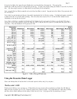
Seagull Transmitter Type
: Select either the FCC US Transmitter (red case) or the EU transmitter (gold case)
depending on which system you have.
Seagull ID:
The Wizard automatically generates an ID for your Seagull system, which you can change in the wizard. The Seagull
ID uniquely attaches your Seagull Transmitter to your Dashboard. This attachment means that it is unlikely that other Seagull
systems at your site will interfere with your system, and it also keeps your data private to some degree. Note that the Seagull system
will not operate if the Seagull Transmitter and Dashboard are set to different ID’s.
Note: The Dashboard ID is displayed in Hexadecimal in the lower right-hand side of the LCD screen at Dashboard power up.
Set Beep on Seagull Keyboard Press:
Check this wizard box if you want a short beep to sound on each press of the Dashboard
buttons. Note that in this mode, selecting Mute All will silence these beeps.
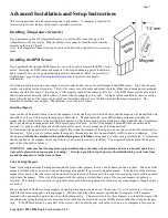
Seagull Power Level (FCC transmitter only):
The Seagull Transmitter supports operation at low (around 8-12 milliwatt) and high
(around 200 milliwatt) power levels. Normally low power is good for indoor use, and high power may be required for outdoor use.
Warning: Always range check your model after changing power levels!
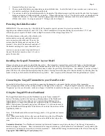
Connecting the Dashboard to USB:
When the Wizard asks you to Connect the Seagull Dashboard, disconnect the Recorder from
the USB connection, and connect the Dashboard as described in the “Seagull Dashboard Receiver Instructions” section above. Note:
Follow the Wizard instructions carefully – if the computer needs to reboot the first time the Dashboard is installed, do so and relaunch
the Wizard after reboot.
After the Dashboard is successfully discovered by your PC, “USB Mode Active” should display on the LCD window. If this does not
happen, see the Troubleshooting section below.
Launching the Dashboard Data Setup Utility:
After the Dashboard is discovered by the PC, the Next button of the Wizard should
ungray, and hitting Next take you to the final page of the Wizard. This page has a button to launch the Dashboard Data Setup Utility.
See the below section on running this utility. Once the utility is successfully run, the Finish button of the Wizard will ungray.
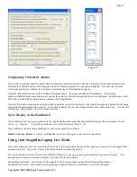
Seagull Dashboard Data Setup Utility Instructions
This utility (the Utility) will appear the first time you run the Seagull Configuration Wizard, and can be re-run by selecting “Tools,
Edit Seagull Display” in the App. This utility is the tool used to bring your Seagull Dashboard to life – it gives you the capability of
configuring all of the items displayed on the LCD screen, setting up alarms, and configuring the Climbrate Alarm settings (Flight
Systems).
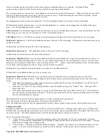
Figure 4 shows the main page of the Utility. The Utility main page is divided into the following section:
Select Data Parameter to Configure on the Dashboard LCD
: This section contains the tools to select what, how and where
parameters are displayed on the LCD pages.
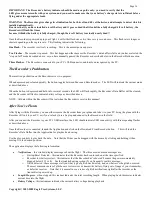
Figure 6 provides a table of the parameters that can be configured with your system.
To select and configure a parameter, choose the parameter to be configured in the “Select Feature to Display” window. A “
o
” next to
an item indicates that this item is already selected for display, and choosing it will allow you to edit the item. After selecting the
parameter, click the “Enable this parameter…” checkbox to enable the parameter to be displayed/configured, or uncheck it to remove
it from the list.
Once the parameter is enabled, choose where the parameter will be displayed by choosing the location in the “Select Display
Location” window. A “
o
” next to the location chosen means it is already in use by this or another parameter. Choosing a location
that is in use already will cause the parameter using it to be disabled.
The window labeled “Enter the label to display..” in this section displays the 3 digit label that will be displayed beside this parameter
on the LCD. You can change this 3 digit label to be whatever you want. For example, if Temperature Sensor 1 was attached to your
Cylinder Head, you might label this parameter “CHT.”
NOTE: If the data for each parameter grows large, such as a large RPM, the middle character in the 3 digit label will be eliminated to
show all the numeric digits in the parameter. For example, “RPM 0” would become “RM 40342” in this case.
Set up alarms (if any) to be triggered by values of the above parameter:
This section contains the tools to set up audible and
visual alarms for many of the displayed parameters.