


-
1 1
-
-
1 2
-
F a u l t s a n d s o l u t i o n s
EC590
O p e r a t i o n a n d d i s p l a y
EC590
7
.
1
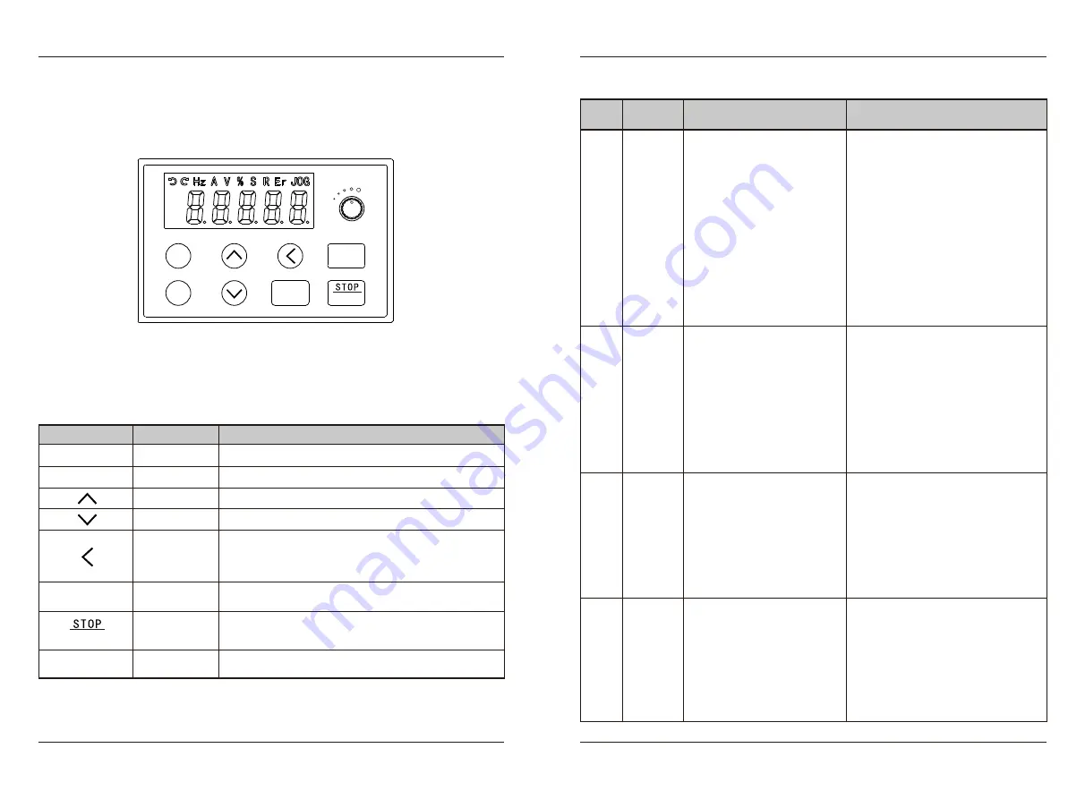
LED operation panel
Note: The built-in keyboard has no panel potentiometer, but the pull-out keyboard includes it.
7
.
Operation and display
7.2 Description of Keys on the LED operation panel
Key
Level
1
main
menu entry or exit.
Enter
the menu interface step by step; Set parameters
Increment of data or function code.
Decrement of data or function code.
Function
In
the
shutdown
display
and
operation display interface,
the display parameters can be selected cyclically. When
modifying a parameter, you can select the modification
bit of it.
In the keyboard operation mode, it is used to run the
operation.
Name
Programming
key
Confirm key
Incremental
key
Decrement key
Shift
key
Running
key
In the running state, press this key to stop; In the fault
alarm state, press this key to reset; Its characteristics
are constrained by function F7-02.
Stop
/
Reset
Select function switching according to F7-01, which can be
defined as source, or fast direction switching.
Multiple
us
key
PRG
SET
RUN
RESET
MF.K
Err03
Overcurrent
during
deceleration
1: The output circuit is grounded
or short circuited.
2: Motor auto-tuning is not
performed.
3: The deceleration time is too
short.
4: The input voltage is too low.
5: A sudden
load is added during
deceleration.
6: The braking unit and braking
resistor are not installed.
7: Subject to external inter-
ference.
1: Eliminate external faults.
2: Perform the motor autotuning.
3: Increase the deceleration time.
4: Adjust the voltage to the normal range.
5: Remove the added load.
6: Install the braking unit and braking
resistor.
7: According to the historical fault
records, if the current value at the time
of fault is far from reaching the over-
current point value, it is necessary to
find the interference suorce.
Err04
Overcurrent
at constant
speed
1: The output circuit is grounded
or short circuited.
2: Motor auto-tuning is not
performed.
3: The input voltage is too low.
4: A sudden load is added during
operation.
5: The AC drive model is of too
small power class.
6: Subject to external inter-
ference.
1: Eliminate external faults.
2: Perform the motor autotuning.
3: Adjust the voltage to the normal range.
4: Remove the added load.
5: Select an AC drive of higher power
class.
6: According to the historical fault
records, if the current value at the time
of fault is far from reaching the over-
current point value, it is necessary to
find the interference suorce.
Err05
Overvoltage
during
acceleration
1: The input voltage is too high.
2: An external force drives the
motor during acceleration.
3: The acceleration time is too
short.
4: The braking unit and braking
resistor are not installed.
5: Subject to external inter-
ference.
1: Adjust the voltage to normal range.
2: Remove the external force or install a
braking resistor.
3: Increase the acceleration time.
4: Install the braking unit and braking
resistor.
5: According to the historical fault
records, if the current value at the time
of fault is far from reaching the over-
current point value, it is necessary to
find the interference suorce.
8.Faults and solutions
Display
Err02
Fault
name
Overcurrent
during
acceleration
Possible causes
1: The output circuit is grounded
or short circuited.
2: Motor auto-tuning is not
performed.
3: The acceleration time is too
short.
4: Manual torque boost or V/F
curve is not appropriate.
5: The input voltage is too low.
6: The startup operation is
performed on the rotating motor.
7: A sudden load is added during
acceleration.
8: The AC drive model is of too
small power class.
9: Subject to external inter-
ference.
Solutions
1: Eliminate external faults.
2: Perform the motor auto
-
tuning.
3: Increase the acceleration time.
4: Adjust the manual torque boost or V/F
curve.
5: Adjust the voltage to the normal range.
6: Select rotational speed tracking
restart or start the motor after it stops.
7: Remove the added load.
8: Select an AC drive of higher power
class.
9: According to the historical fault
records, if the current value at the time
of fault is far from reaching the over-
current point value, it is necessary to
find the interference suorce.
MF.K
RESET
PRG
SET
RUN


