


EC5000
-
102
-
-
103
-
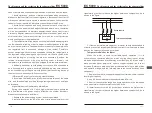
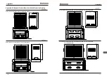
MODBUS Communication Protocol
6
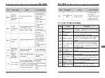
2.RTU Mode:
Inquiry Message Format: Response Message Format:
ADR
01H
CMD
10H
00H
Data
Starting Address
1DH
00H
Data Quantity
(Word)
02H
CRC Check Low
D1
CRC Check High
CE
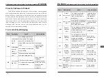
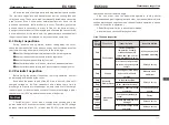
6.3 Check Value:
■
Check Code (LRC Check) of ASCII Mode
Check code (LRC Check) is the total sum from of Address to the end of
Data content.
For example: for the Check code of inquiry message in 3.3.1
01H + 03H + 21H + 02H + 00H + 02H = 29H, then take the complement of
“2”, and we get D7H.
■
Check code (CRC Check) of RTU Mode
Check code is calculated from Address to the end of Data content. The
Operation rules are as follows:
Step 1: Set 16
-
bit register (CRC register) = FFFFH.
Step 2: Perform “Exclusive OR” on the first 8-bit byte message instruction
and lower 16-bit CRC register and save the value obtained to CRC register.
Step 3: Right Shift CRC register and set the most significant bit with “0”;
ADR
01H
CMD
10H
00H
Data
Starting Address
1DH
00H
Data Quantity
(Word)
02H
Data
04H
13H
First
Data
88H
0FH
Second
Data
A0H
CRC Check Low
B2
CRC Check High
1C
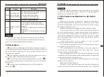
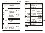
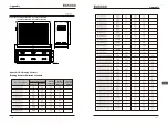
1. ASCII Mode:
Inquiry Message Format: Response Message Format :
STX
‘:’
‘0’
ADR 1
ADR 0
‘1’
CMD 1
‘1’
CMD 0
‘0’
‘0’
‘0’
‘1’
Data Starting
Address
‘D’
‘0’
‘0’
‘0’
Data Quantity
(Word)
‘2’
‘D’
LRC Check
‘0’
CR
END
LF
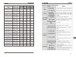
STX
‘:’
‘0’
ADR 1
ADR 0
‘1’
‘1’
CMD 1
CMD 0
‘0’
‘0’
‘0’
‘1’
Data Starting
Address
‘D’
‘0’
‘0’
‘0’
Data Quantity
(Word)
‘2’
‘0’
Data Quantity
(Byte)
‘4’
‘1’
‘3’
‘8’
First Data
‘8’
‘0’
‘F’
‘A’
Second Data
‘0’
‘8’
LRC Che ck
‘2’
CR
END
LF
EC5000
■
Command Code: 10H, Write several data in succession
For example: Change the multiple speed setting of driver (Address 01H)
001DH=50.00(1388H) and 001EH=40.00(0FA0H)
MODBUS Communication Protocol