


EC5000
-
46
-
-
47
-
Description of Functional Parameter
5
EC5000
Description of Functional Parameter
Function
Parameters
Name
Description
Setting
range
Default Page Address
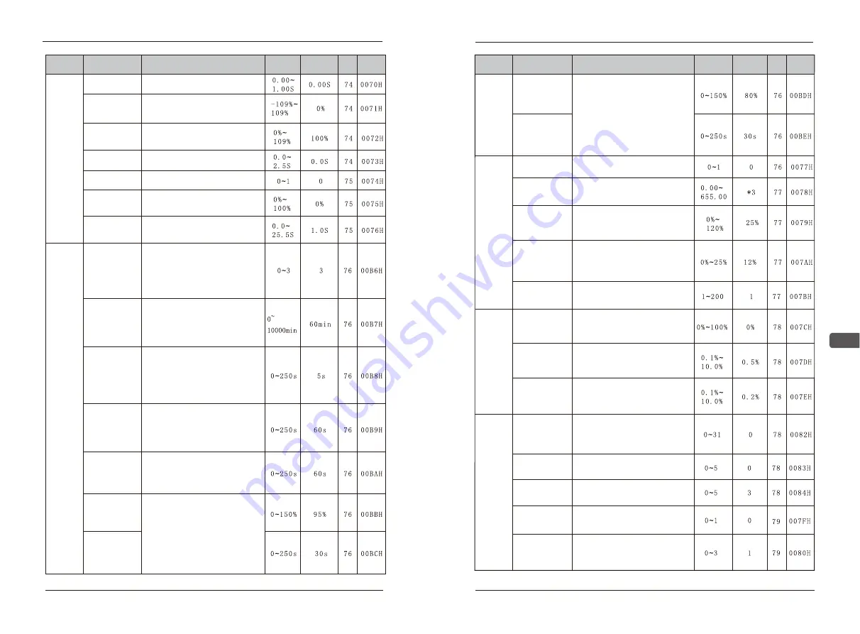
D05 PID
Derivative time
Set D control proportion increase.
If set to be 0.0, no D control.
PID
Control
Constant
pressure
water
supply
parameters
D12 Stall
prevention
during
deceleration
0~2: The number of opening pumps
in the constant pressure water
supply control
3: close the pump control
The factory default is 3,so if use
constant pressure water supply,
please set D12 to be 0~2.
D06 PID
Feedback bias
value
Deviation adjustment to frequency
order control by PID.
Unit:1%
D07 Limit of PID
integral value
Set the up limits value of frequency
output controlled by I.
Unit:1%
D08 Feedback
filter time
Set the one time delay data of
frequency order controlled by PID.
D09 Feedback
loss detection
0:Detection is disabled
1:Detection is enabled
D10 Feedback
loss detection
level
Feedback lost test standard (PID),
set losing grade of PID feedback
with unit of 1%.
D11 PID
Feedback
loss time
Delayed feedback lost time (PID),
set testing PID feedback lost time.
D13 Rotation
time
When the two auxiliary pumps only
one work, in order to average the
time of working for every pump, the
working time for one pump is D13
and then change to work for another
one.
D14 Interlock
time
When the two auxiliary pumps only
one work, in order to average the
time of working for every pump, the
working time for one pump is D13
and then change to work for another
one. This time is the middle waiting
time.
D15 High-speed
working
When the water consumption is
increasing ,the AC drive is working
on the max frequency, when
it reach the setting time D15, the
corresponding multi-functional
contact action
D16 Low-speed
working
When the water consumption is
reducing, the AC drive is working
on the min frequency, when it reach
the setting time D16, the correspon-
ding multi-functional contact action.
D17 Stopping
Standard
When the water consumption is
reducing, all of the auxiliary pumps
have turned off, the main pump are
working on the min frequency, when
meet the following conditions:
1:(setting frequency/max frequency)*
D17<PID feedback value
2:The time exceed D18
The AC drive stops output, and be
in sleep mode.
D18 Stopping
Time
Function
Parameters
Name
Description
Setting
range
Default Page Address
Constant
pressure
water
supply
parameters
D19 Wake-up
standard
The AC drive is in sleep mode.
When the water consumption is
increasing, the pressure of the
pump will reduce accordingly. When
meet the following conditions:
1: (setting frequency/max frequency)
*D19>PID feedback value
2: The time exceed D20
The AV drive begins outputting, the
pump starts working.
D20 Wake-up
time
E04 Energy
saving voltage
lower limit
at 6Hz
E05 Time of
average kW -
energy saving
Energy
saving
control
E01 Energy
saving selection
0:energy saving is disabled
1:energy saving is enabled
E02 Elapsed
timer selection
Set the motor coefficient in max
frequency , the factory settings are
set according to the motor standard.
In a 6Hz energy saving operation
mode set to count the lower limit
value of the output voltage instru-
ction value, the rated voltage is
100%.
E06 Limit
voltage
To control voltage through best
running. The rated voltage of the
motor is 100%. It can not running
well if set percentage to be 0.
Energy
saving
operation
control
E03 Energy
saving voltage
lower limit
at 60Hz
Set the motor coefficient in max
frequency , the factory settings are
set according to the motor standard.
Set average power computation
time in energy saving mode.
E07 100%
Anti-jump
Best start running voltage variation
amplitude of voltage is set at 100%,
with unit of 0.1% ,the motor rated
voltage is 100%
E08 5%
Anti-jump
Best start running voltage variation
amplitude of voltage is set at 5%,
with unit of 0.1% ,the motor rated
voltage is 5%
F01 MODBUS
slave address
0:AC drive break away from RS485
general control address, non contr-
olled address.
1~31: controlled address of AC drive
RS485 communication.
RS485
communi-
cation
control
F02 MODBUS
BPS selection
0: 1200BPS 1:2400BPS
2:4800BPS 3:9600BPS
4: 19200BPS 5: 38400BPS
F03 MODBUS
parity selection
0:7N2 For ASCII 1:7E1 For ASCII
2:7O1 For ASCII 3:8N2 For RTU
4:8E1 For RTU 5:8O1 For RTU
F04 MODBUS
time over
detection
0:Time over detection is disabled
1:Time over detection is enabled
F05 MODBUS
stop method at
communication
error CE
0:Ramp to stop-Decel 1(fault)
1:Coast to stop(fault)
2:Ramp to stop-Decel 2 (fault)
3:Continue operation(alarm)