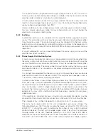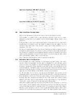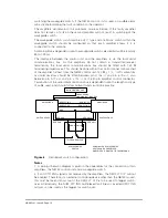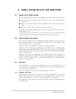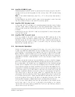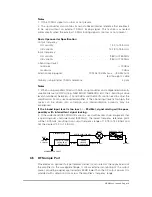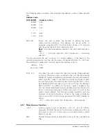
Fault Code
MUX
3210
Fault Type
Reset Code
1101
Upconverter fault
I
1100
Baseplate over-temperature condition
M
1011
TWT Collector over-temperature condition
M
1010
Cooling fan #2 fault
P
1001
Cooling fan #1 fault
P
1000
Heater fault
P
0111
HV fault
A
0110
DC bus fault
P
0101
PFC fault
P
0100
External interlock trip
M
0011
Reflected power trip
A
0010
Mean helix over-current trip
A
0001
Peak helix over-current trip
A
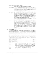
Reset Code Description
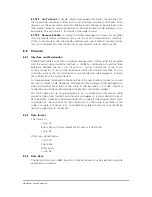
A (Automatic reset). Units that exhibit faults with this reset code will be immediately
removed from the XMIT mode and placed into the STBY mode. The unit will
automatically attempt to reset to the XMIT mode after 3 seconds; if this fails the unit
will attempt a further two reset cycles. If after the three reset attempts the amplifier
still exhibits the fault condition, the unit will remain in the STBY mode for 4 minutes
before returning to the OFF mode, unless the fault clears and the XMIT mode is
reselected.
I (Advisory) Units that exhibit faults with this reset code will remain in the XMIT
mode; the fault display will remain until the fault clears.
M (Manual reset). Units that exhibit faults with this reset code will be immediately
removed from the XMIT mode and placed into the STBY mode. The unit will remain
in this mode for a period of 4 minutes before returning to the OFF mode, unless the
fault clears and the XMIT mode is reselected.
P (Prime power reset). Units that exhibit faults with this reset code will be
immediately removed from the XMIT mode and placed into the OFF mode. If the
fault is seen to clear, the mains supply should be removed for nominally 10 seconds
before reapplying to reset the trip.
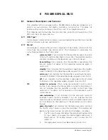
5.2.2
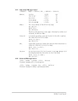
Indicator Outputs - Type 2
Normally open relay contact outputs switched to GND (pin P on the user interface
connector) when condition is false.
Example
Unit is operating normally with no fault condition when pin k on the user
interface connector is closed to pin P.
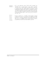
RED FLT O/P
Part of the redundant switch control facility. Indicates that the unit
has suffered a low power alarm or a fault condition that has resulted
in removal from the XMIT mode. This output would normally be
connected to the RED FLT I/P (pin t on the user interface
connector) of the other amplifier in the redundant switch system.
Note:
Only active if an AUTO ENA input has been received by the amplifier.
HBN63xx-1, Issue 8, Page 22

