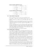
It is important when using lower mains supply voltage sources of 110 V and 120 V
nominal, to ensure that the required voltage is available at the input connector of the
amplifier under conditions of maximum current demand.
It is also important to ensure that for any supply selected, the mains supply source no
load to full load voltage drop is less than 10 V rms. On full load, the amplifier mains
supply voltage must be greater than 99 V.
Under conditions of a low voltage power source with long power connection leads,
this may require selecting a cable for low voltage drop and not just basing the
selection on a nominal current rating.
3.4.2
Earthing
A protective earth must be connected to the amplifier before applying the mains
supply. This protective earth must only be removed after disconnecting the amplifier
from the mains supply. The protective earth must be connected to the local system
earth point, must be capable of carrying 30 A and must conform to the regulations in
the British Standard Codes of Practice BS7430 (1991 Earthing), or equivalent national
regulations.
A supply wiring earth can be connected between the mains supply source and the
amplifier rear panel connector.
3.4.3
Mains Supply Distribution System
A mains supply disconnection device must be provided to isolate the amplifier from
the mains supply source. Either a socket outlet or a two-pole isolation switch must be
used as the mains supply disconnection device. It must be installed near the amplifier
and be easily accessible. The mains connector must not be used as the mains supply
disconnection device. It is provided for convenience during installation and for ease
of operation.
It is strongly recommended that the mains supply for the amplifier is fed via a double
pole Residual Current Circuit Breaker (RCCB). The amplifier earth leakage current is
5
6 mA rms under nominal operating conditions.
In some circumstances on low voltage 3-phase systems (e.g. 115 V line to neutral and
200 V line to line), it may be preferable to operate the amplifier bi-phase. In this case,
the amplifier may be connected across any two lines of the 3-phase system to obtain
what is effectively a 200 V single phase source. Under these circumstances the
neutral of the 3-phase system is not connected to the amplifier. With smaller, 3-phase
generators this may offer a method of partially balancing a number of lower power
single phase loads.
If the amplifier is connected bi-phase, an external 2-pole protection device must be
provided that disconnects both line connections in the event of a fault on either line.
This equipment has not been designed for connection to an IT power system.
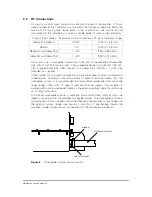
The mains input surge current for this unit is dependent upon mains voltage. The
following table shows the I
2
t products during the ’power up’ phase for 110/120 V and
220/240 V; it should be used to determine the rating of any current overload
protection devices. The half cycle average surge current is less than the maximum
running current of the unit, therefore typically a 13 A HRC fuse to BS 1362 is
adequate for the over-current protection of each amplifier (this can be reduced to a
10 A HRC fuse to BS 1362 if the unit is to be used on high mains voltage supplies).
HBN63xx-1, Issue 8, Page 14


