3.2
RF Connections
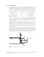
RF input is via an N type connector mounted on the end of the amplifier. RF input
signals applied to this connector must be within the frequency range and below the
maximum RF input power levels given in the specification (see section 8) and
summarised in the table below. Ensure a suitable grade of cable is used externally.
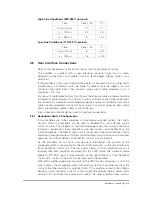
Product type number
Maximum RF input drive level RF input frequency range
N63xx and N63xxD
10 mW
13.75 to 14.5 GHz
N63xxC
1 W
13.75 to 14.5 GHz
N63xxUA and N63xxDUA
1 mW
950 to 1450 MHz
N63xxUB and N63xxDUB
1 mW
950 to 1700 MHz
RF output is via a waveguide connection on the end of the amplifier. Waveguides
type WG17 or WR75 may be used. The waveguide flange (type 154 IEC UBR 120,
with 4 tapped holes 6-32 UNC) requires four screws 6-32 UNC-2A x
1
/
2
-inch fully
threaded, as supplied.
If the amplifier is to be used in applications where it is exposed to rain or subjected to
condensation, all attempts should be made to prevent moisture ingress into the
waveguide system. It is recommended that all external waveguide joints are made
using flanges fitted with ’O’ rings to prevent moisture ingress. The amplifier is
supplied with a plain waveguide flange, so the external mating flange should include
an ’O’-ring and groove.
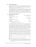
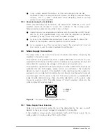
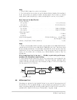
An optional waveguide window is available, which when fitted correctly stops the
ingress of moisture into the amplifier waveguide system. The waveguide window is
approximately 10 mm in length and is fitted between the amplifier output flange and
the external system flange (see figure 4), with the ‘O’-ring groove toward the
amplifier. Longer fixing screws are supplied with the waveguide window kit.
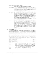
Figure 4
Waveguide window option position
"
"
WINDOW
EXTERNAL WAVEGUIDE
RF OUTPUT FLANGE
"
HBN63xx-1, Issue 8, Page 10


